

TerraPhoto User Guide
Define color points
Define color points command starts the color point mode. This includes opening of the Color points menu and additional processing steps depending on the specified color point mode:
•Ground ortho - creation of a ground model, preview of rectified images.
•Point cloud - on-the-fly extraction of color values for each point, display of the point cloud.
The Color points menu allows you to create color points and to define different types of correction polygons that improve the quality of the final ortho mosaic or a colored point cloud.
Color points for the rectification of images or orthophoto production require a ground model. Therefore, the corresponding color point mode is only available, if ground points are loaded into TerraPhoto.
Color points for point clouds require a TerraScan project that manages the point cloud and a point cloud format that is able to store color values, image numbers, and normal vectors/dimensions for each point. The storage of all these attributes is only possible in TerraScan FastBinary format.
The concept of color points and commands of the Color points menu are described in detail in Chapter Color Points and Selection Shapes.
To start the color point mode for (ortho) rectification:
1. Select Define color points from the Rectify pulldown menu.
This opens the Color Point Setting dialog:
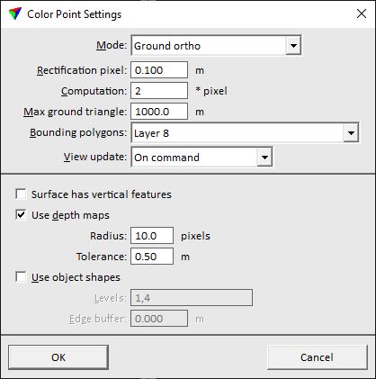
2. Select Ground ortho in the Mode list.
3. Define settings and click OK.
This starts the color point mode.
SETTING |
EFFECT |
|---|---|
Rectification pixel |
Intended pixel size of the final orthophoto mosaic. |
Computation |
Pixel size scale factor for color point computation. Color points and selection shapes do not need to be computed at the full resolution of the final orthophoto. It is recommended to use a factor of 2 or 3 in order to make computation processes faster. |
Max ground triangle |
Maximum triangle length in the ground model. |
Bounding polygons |
If on, the area available for color points is limited by the polygon(s) drawn on the given CAD file level. The list contains all levels with elements in the CAD file. |
View update |
Method of updating the view display after modifications to color points and selection shapes: •On command - the display must be updated manually. •Automatic - the display is updated automatically after each modification. |
Surface has vertical features |
Switch this on if the surface model includes vertical structures. If on, occlusions caused by the triangulated surface of points loaded to TerraPhoto is considered in image selection. |
Use depth maps |
If on, depth maps are used to create a true orthophotos preview without vector models. The depth maps should be computed only from point classes representing high objects, such as building roofs and bridges. |
Radius |
Radius checked in image depth map to find out if the rectification surface is visible or occluded. This is only active if Use depth maps is switched on. |
Tolerance |
Allowed depth difference between a rectification pixel and depth map before the point is considered occluded. If the depth of a rectification pixel is bigger than depth map value and tolerance together, pixel in the image is considered occluded and some other image is used in rectification. This is only active if Use depth maps is switched on. |
Use object shapes |
If on, object shapes on the given levels are used to create a true orthophoto preview. |
Levels |
Number(s) of CAD file levels that contain 3D objects for true orthophotos. Separate several levels by comma. This is only active if Use object shapes is switched on. |
Edge buffer |
Distance from the edge of a 3D object within which object pixels are not rectified on the ground. The prevents, for example, roof pixels to be rectified on the ground next to buildings. This is only active if Use object shapes is switched on. |
To start the color point mode for point clouds:
1. Select Define color points command from the Rectify pulldown menu.
This opens the Color Point Setting dialog:
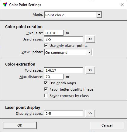
2. Select Point cloud in the Mode list.
3. Define settings and click OK.
This starts the color point mode.
SETTING |
EFFECT |
|---|---|
Pixel size |
Approximate pixel size of raw images. Determines the size of a color point. |
Use classes |
Point classes used for color point creation. Exclude classes with non-planar objects, such as poles, wires, etc. |
|
Opens the Select classes dialog which contains the list of active classes in TerraScan. You can select multiple source classes from the list that are then used in the Use classes field. |
Use only planar points |
If on, only points with dimension attribute Planar are used for color point creation. |
View update |
Method of updating the view display after modifications to color points and selection shapes: •On command - the display must be updated manually. •Automatic - the display is updated automatically after each modification. |
To classes |
Point classes for which color values are extracted on-the-fly for displaying points in the color point mode. |
|
Opens the Select classes dialog which contains the list of active classes in TerraScan. You can select multiple source classes from the list that are then used in the To classes field. |
Max distance |
Maximum distance between a raw image and a laser point. Images outside that distance are not considered for color extraction. |
Use depth maps |
If on, depth maps files are included in the color extraction process. |
Favor better quality images |
If on, the quality attribute stored for raw images in an image list is considered in the color extraction process. |
Favor cameras by class |
If on, the settings in the TerraPhoto mission file related to favoring cameras for coloring points are considered in the color extraction process. |
Display classes |
Point classes that are displayed in color point mode. |
|
Opens the Select classes dialog which contains the list of active classes in TerraScan. You can select multiple source classes from the list that are then used in the Display classes field. |
