

TerraPhoto User Guide
Compute shadow maps
Not Lite
Compute shadow maps command creates raster files for each image of the active image list. The pixels in the shadow map files encode shadow areas close to high objects, such as high vegetation or buildings. The objects are represented by laser points and (optional) 3D vector elements.
Shadow maps are stored as TIFF files in the \TEMP directory of the mission. They are used for automatic tie point and color point placement.
To compute shadow maps:
1. Select Compute shadow maps command from the Utility pulldown menu.
The Compute Shadow Maps dialog opens:
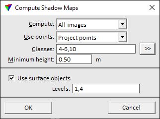
2. Define settings and click OK.
This starts the computation process. Depending on the amount of images and selected settings, the process may take some time. A progress bar shows the progress of the process.
SETTING |
EFFECT |
|---|---|
Compute |
Images for which shadow maps are created: •All - all images of the active image list. •Selected - images selected in the active image list. •<camera name> - images captured by the selected camera. |
Use points |
Determines the laser data source for computing shadow maps: •Loaded points - points that are loaded in TerraScan are used. This is only active if points are loaded in TerraScan. •Project points - points of the active project in TerraScan are used. This is only active if a project is loaded in TerraScan. |
Classes |
Defines which points are used related to classes. |
|
Opens the Select classes dialog which contains the list of active classes in TerraScan. You can select multiple source classes from the list that are then used in the Classes field. |
Minimum height |
Minimum height of objects that are considered in shadow maps. |
Use surface objects |
If on, 3D vector elements on the given CAD file Levels are included in the shadow map computation. |
