

TerraScan User Guide
Vectorize Wall Polygons
Not UAV
 Vectorize Wall Polygons tool draws planar wall polygons into the CAD file. The tool identifies points on the same vertical surface, and draws polygon shapes outlining the points.
The source classes for this tool should contain good density and coverage of points on the vertical target wall surfaces. Thus, this tool is mainly suitable for data captured with TLS, handheld or other mobile scanners, or oblique oriented UAV systems.
The Inspect Elements tool may be used to check and modify the wall polygons in an organized way.
To vectorize wall polygons:
1. Classify wall points.
2. Select the Vectorize Wall Polygons tool.
This opens the Vectorize Wall Polygons dialog:
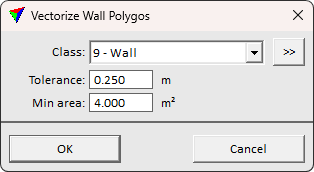
3. Define settings and click OK.
This draws the polygon elements into the CAD file. The polygons are drawn on the active level with the active symbology settings of the CAD file.
SETTING |
EFFECT |
|---|---|
Class |
Point class(es) that are considered for the wall polygon extraction. The class(es) must contain good number of points on the vertical wall surfaces. The classes may contain other points, too, but restricting the search to wall points only can speed up the process. |
|
Opens the Select classes dialog which contains the list of active classes in TerraScan. You can select multiple source classes from the list that are then used in the Class field. |
Tolerance |
Defines how closely a point must match a plane equation to belong to wall plane. |
Min area |
Minimum area of a wall polygon. Smaller findings are discarded. |
