

TerraScan User Guide
Inspect Elements
 Inspect Elements tool supports the systematic check of vector elements in a CAD file. It provides a list of elements from which you can select one element after the other.
The tool includes view settings that define CAD file views displaying the selected element in different view orientations. The selected element is automatically centered in these views.
To inspect vector elements:
1. Select the elements you want to check.
2. Select the Inspect Elements tool.
This opens the Inspect Elements dialog:

SETTING |
EFFECT |
|---|---|
Top view |
CAD view that displays the selected element in a top view. |
Second top view |
CAD view that displays the selected element in a top view. |
Front view |
CAD view that displays the selected element in a front section view. The cross section is 90 degree rotated compared with the Right view. |
Right view |
CAD view that displays the selected element in a right section view. The cross section is 90 degree rotated compared with the Front view. |
Plane section view |
CAD view that displays a section fit to element. This is useful, for example, for validating building wall or roof polygons appearing in arbitrary orientations. |
Isometric view |
CAD view that displays the selected element in an isometric view. |
Camera view |
CAD view that displays the selected element in a camera view. The view can display images that are referenced by an active image list in TerraPhoto. |
Fit view |
If on, the selected element is automatically fitted in the view. |
Depth |
The cross section thickness to display. |
Add |
Create new action button definition. |
Edit |
Modify selected action button definition. |
Delete |
Remove selected action button. |
3. Define the view settings and element action buttons and click OK.
This opens another Inspect Elements dialog that contains the list of all selected elements:
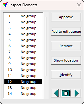
4. Select a line in the list of elements.
This centers the selected element in all CAD file views defined in the tool’s View settings. You can use the action buttons of the dialog to apply the shortcut action on the active element.
SETTING |
EFFECT |
|---|---|
<Action Button> |
Perform the action specified in element action button definition. |
Show location |
Select a line in the list, click on the button and move the mouse pointer inside a CAD file view. This highlights the selected element in the view. |
Identify |
Click on the button and identify an element with a data click in a CAD file view. This selects the corresponding line in the list. |
|
Moves one image backward in the active image list and displays the new image in the camera view. |
|
Click on the button and move the mouse pointer inside a CAD file view. The image closest to the mouse pointer is highlighted. Select an image for the camera view display with a data click. |
|
Moves one image forward in the active image list and displays the new image in the camera view. |


The element actions define shortcut buttons to streamline the vector element checking process. The shortcuts can modify the vector elements, or simply remove the elements from the active list to accept the selected element.
To define element action:
1. Press Add or Edit -buttons in Inspect elements tool settings Action button section
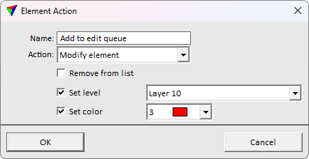
This opens the Element action dialog for defining the action button:
SETTING |
EFFECT |
|---|---|
Name |
The text to display on the button |
Action |
The action to perform on button press. No action, Modify element or Delete element. |
Remove from list |
Removes the selected element from the list. The CAD element itself is not deleted but the element row is removed from the list. |
Set level |
If on, the action button press moves the active element to the given CAD file level. This is available only if Action is set to Modify element. |
Set color |
If on, the action button press applies the given line color to the active element. The list contains the active color table of the CAD file. This is available only if Action is set to Modify element. |
2. Define the view settings and click OK.
This adds the definition to the list of action buttons. The defined buttons appear to the Inspect elements dialog after accepting the setting definition.