

TerraScan User Guide
Vectorize Tunnel Sections
Not UAV
 Vectorize Tunnel Sections tool draws tunnel cross sections into the CAD file. The sections are drawn as line string elements which are fitted to the cross section provided by the point cloud. The tool requires a 3D linear element that runs along the approximate center of the tunnel. The tool does not try to create closed line strings for the sections.
Optionally, the tool draws additional line elements as markers for the section location. These horizontal marker lines are drawn at the alignment element elevation and extended up to the length of the given offset from alignment setting. The line may be useful for creating a vertical section at a tunnel cross section location.
Before vectorizing tunnel sections, it may be useful the classify the points on the tunnel floor, roof and walls by using the Tunnel surfaces classification routine.
The Check Tunnel Sections tool may be used to check and modify the tunnel sections in an organized and automated way.
To vectorize tunnel sections:
1. Select the 3D alignment element.
2. Select the Vectorize Tunnel Sections tool.
This opens the Vectorize Tunnel Sections dialog:
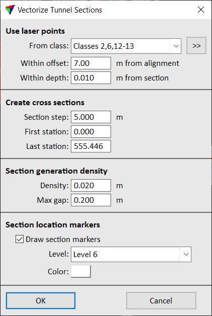
3. Define settings and click OK.
This draws the sections and possibly the location markers into the CAD file. The sections are created as line string elements and drawn on the active level with the active symbology settings of the CAD file.
SETTING |
EFFECT |
|---|---|
From class |
Point class(es) that are considered for the section line fitting. |
|
Opens the Select classes dialog which contains the list of active classes in TerraScan. You can select multiple source classes from the list that are then used in the From class field. |
Within offset |
Maximum distance of points from the alignment element that are considered for the section line fitting. Determines also the length of the section marker lines left and right from the alignment. |
Within depth |
Depth of a tunnel cross section within which points are used for the section line fitting. |
Section step |
Distance between consecutive sections. |
First station |
Location of the first cross section along the alignment element. |
Last station |
Location of the last cross section along the alignment element. By default, the software suggests the last possible location at the end of the alignment element. |
Density |
Minimum length of a line segment along the cross section line string. Determines the complexity of the cross section line string element. |
Max gap |
Maximum length of a gap in the point cloud cross section that is ignored for the section drawing. A larger gap breaks the section line string element. |
Draw section markers |
If on, an additional line element is drawn in the CAD file at the location of the cross section. |
Level |
CAD file level on which the section marker lines are drawn. This is active only if Draw section markers is switched on. |
Color |
Color used for drawing the section marker lines. Uses the active color table of the CAD file. This is active only if Draw section markers is switched on. |
