

TerraScan User Guide
Label Towers
 Label Towers tool draws a label for each tower represented by a vertex of the active tower string element. The label is drawn as cell element into the CAD file. The label is displayed in all views in a way that it is readable independently of the view type and rotation.
The location of the label is determined by the vertices of the tower string element and offset values. A positive offset value places the label elements on the right side of the tower string, a negative value on the left side. In addition, an elevation offset can be applied. Active text size, level, and symbology settings of the CAD file are used for drawing the labels.
To place labels for tower locations:
1. Activate a tower string element using the Activate Powerline tool.
2. Define settings for texts using the CAD platform Text tools. Set the active level and symbology settings.
3. Select the Label Towers tool.
This opens the Label Towers dialog:
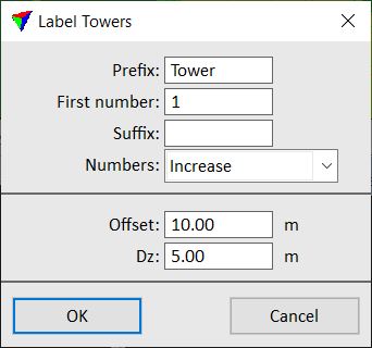
4. Define settings and click OK.
This draws the labels into the CAD file.
SETTING |
EFFECT |
|---|---|
Prefix |
Text that is added before the tower number. |
First number |
Number of the first tower. |
Suffix |
Text that is added after the tower number. |
Numbers |
Method of numbering the towers along the tower string element: Increase or Decrease. |
Offset |
Horizontal offset of the label from the tower location. Measured between the tower string vertex and the center point of the text element. |
Dz |
Vertical offset of the label from a tower location. Measured between the tower string vertex and the center point of the text element. |
You can undo the placement of tower labels by using the Undo command of the CAD platform.