

TerraScan User Guide
Label Clearance
 Label Clearance tool labels the smallest distance between two point classes within a given area. The area is defined by one or more selected polygons.
The tool expects that a distance from ground value is computed for the points in the source class for clearance analysis. The value can be computed by using the Compute distance command for loaded points or the Compute distance macro action. Within each polygon, the tool finds the point with the smallest distance value in the source class. It classifies the point, and draws a line marker and a text element into the CAD file. The vertical line marker marks the location of the smallest distance. The text element shows the corresponding distance value.
The readability of the text element is determined by a given rotation setting. It is either readable in top views or in section views. If trajectory information is loaded into TerraScan, the text is automatically rotated in the direction of the system movement. If no trajectory information is available, the text can be rotated according to the drawing direction of the polygon that defines the area for clearance analysis. For example, if the first edge of the polygon is drawn in East-West direction, the text element is rotated to be readable in East-West direction.
The Label Clearance tool runs on points loaded into TerraScan.
To label the clearance:
1. Draw a polygon around each location for which to label the clearance.
2. Select all polygons for which to label the clearance.
3. Select the Label Clearance tool.
This opens the Label Clearance dialog:
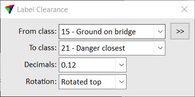
4. Define settings.
5. Confirm the polygon selection with a data click inside a view.
This classifies the point with the smallest distance value inside each polygon. In addition, it creates a text element showing the distance value and a vertical line element showing the location of the smallest distance. The text and line elements are drawn on the active level using active symbology settings of the CAD file.
SETTING |
EFFECT |
|---|---|
From class |
Point class(es) from which to detect the smallest distance value. |
|
Opens the Select classes dialog which contains the list of active classes in TerraScan. You can select multiple source classes from the list that are then used in the From class field. |
To class |
Target class into which the point with the smallest distance value is classified. The list contains the active classes in TerraScan. |
Decimals |
Amount of decimals shown in the label of the smallest distance. Zero to three decimals are available. |
Rotation |
Determines the readability of the label: •From view - the text element is readable in the view where the final confirmation data click is entered •Top - the text element is readable in a top view with north direction being up. •Top trajectory - the text element is readable in a top view. It is rotated horizontally in drive/flight direction (if trajectory information is loaded into TerraScan) or in the direction of the first edge drawn for the polygon if trajectories are not available. •Section trajectory - the text element is readable in a cross section view. The viewing direction is in drive/flight direction (if trajectory information is loaded into TerraScan) or in the direction of the first edge drawn for the polygon if trajectories are not available. •Section trajectory - the text element is readable in a cross section view. The label is facing the direction of the first edge of the boundary polygon. |

You can undo the labelling of clearance by using the Undo command of the CAD platform (text and line placement) and the Undo command from the Point pulldown menu of TerraScan (point classification).