

TerraScan User Guide
Label Alignment Curvature
 Label Alignment Curvature tool computes the radius of curves of 3D line elements. It places text elements that show the horizontal or vertical curvature radius.
For roads, the curvature radius determines the best value for the side slope inside a curve. Therefore, the tool supports the analysis of road surface properties.
The tool requires an alignment element, which can be the centerline of a road, railroad, etc. derived from trajectory lines or any other representative line element.
To create labels for the radius of curves:
1. Select the alignment element with any Selection tool.
2. Select Label Alignment Curvature tool.
This opens the Label Alignment Curvature dialog:
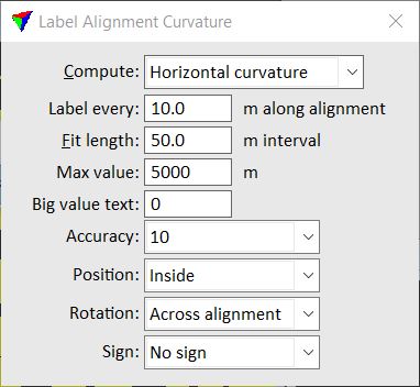
3. Define settings.
4. Place a data click inside a CAD view.
This creates the curvature labels. The software draws text elements along the alignment element. The level, color, and text size of the labels are determined by the active symbology and text size settings in the CAD file.
An information dialog shows the number of created curvature labels.
SETTING |
EFFECT |
|---|---|
Compute |
Curvature to compute: Horizontal curvature or Vertical curvature. |
Label every |
Distance between locations along the alignment element where the software places a curvature label. |
Fit length |
Length of an interval along the alignment element from which the software computes the curvature radius. From each labeling point, the software uses half of the given length forward and backward along the element and fits a circle. The radius of the circle determines the curvature radius at this labeling point. |
Max value |
Maximum curvature radius that is labeled. |
Big value text |
Text used for radius values larger than the given Max value. |
Accuracy |
Accuracy of curvature labels. Values are rounded to the given accuracy, e.g. to the closest 10m value. |
Position |
Determines the placement location of the labels relative to the alignment element: •On alignment - on the alignment element. •Left - left of the alignment according to digitization direction. •Right - right of the alignment according to digitization direction. •Inside - on the inside of a curve. •Outside - on the outside of a curve. |
Rotation |
Determines the placement rotation of the labels relative to the alignment element: •Along alignment - reading direction is parallel to the alignment. •Across alignment - reading direction is perpendicular to the alignment. |
Sign |
Sign added in front of the curvature radius value: •No sign - no sign is added. •Left negative - a minus sign is added to left-hand curves. •Right negative - a minus sign is added to right-hand curves. |
You can undo the creation of curvature labels by using the Undo command of the CAD platform.