

TerraScan User Guide
Label Section Parameters
 Label Section Parameters tool labels the selected section parameters to the CAD file. Section positions are defined with data clicks.
The available section parameters are described in topic Compute road parameters.
The Label Section Parameters tool calculates parameters from points loaded into TerraScan.
To label section parameters:
1. Select the Label section parameters tool.
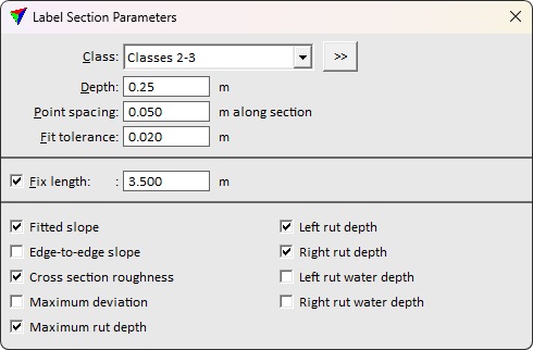
This opens the Label Section Parameters dialog:
2. Define settings.
3. Place data click in top view to define the start point of the section.
4. Place another data click to define the end point of the section. If Fix length is enabled, the end points define the travel direction instead.
OR
1. Select an alignment line defining the travel direction perpendicular to the sections.
2. Select the Label section parameters tool.
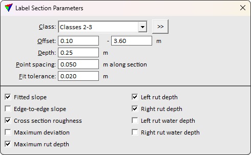
This opens the Label Section Parameters dialog:
3. Define settings.
4. Place data click to define the section position along the alignment element.
This labels the section and the parameters to the CAD file. The section line respects the active symbology. Symbology of the label elements is defined in road section parameters settings.
SETTING |
EFFECT |
|---|---|
Class |
Point class(es) defining the section surface. |
|
Opens the Select classes dialog which contains the list of active classes in TerraScan. You can select multiple source classes from the list that are then used in the Class field. |
Offset |
Left and right endpoint offset from the alignment element. This is available only if alignment element was selected before activating the tool. |
Depth |
Determines the section depth for computing the parameters. |
Point spacing |
Determines the readability of the label: •Top - the text element is readable in a top view with north direction being up. •Rotated top - the text element is readable in a top view. It is rotated horizontally in drive/flight direction (if trajectory information is loaded into TerraScan) or in the direction of the first edge drawn for the polygon. •Cross section - the text element is readable in a cross section view. The viewing direction is in drive/flight direction (if trajectory information is loaded into TerraScan) or in the direction of the first edge drawn for the polygon. |
Fit tolerance |
Defines how well a fitted cross section line follows the points. |
Fix length |
If on, specifies the length of the section used to compute the section parameters. |
<Section parameter name> |
If on, parameter value is measured from the point cloud section and labeled to the CAD file. |

You can undo the labelling of clearance by using the Undo command of the CAD platform (text and line placement) and the Undo command from the Point pulldown menu of TerraScan (point classification).