

TerraScan User Guide
Create Void Polygons
 Create Void Polygons tool creates rectangular shape elements that bound empty areas in the point cloud. The tool can be useful for data quality assurance and improvements. The polygon boundaries help to identify locations with data missing. To fill the holes, data from some other measurement source, like photogrammetric measurements, can be imported to inside the found void areas. Additionally, Cut Overlap tool can be used to harmonize the imported points with the original data.
Void polygons do not store any attribute information. The elements are created following the active drawing settings of the CAD platform.
To create void polygons:
1. Select the Create Void Polygons tool.
The Create Void Polygons dialog opens:
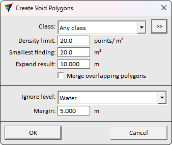
2. Define settings and click OK.
This starts the automatic void extraction process. The tool creates the shape elements to the CAD file using the active drawing settings.
SETTING |
EFFECT |
|---|---|
Class |
Point class(es) from which to find the void areas. |
Density limit |
The expected point density. Lower density areas will be labeled. |
Smallest finding |
Required void size. Areas of the set size and larger are labeled. Use bigger value to filter irrelevant findings. |
Expand result |
The buffer size to expand the extracted void shapes. |
Merge overlapping polygons |
If on, the tool merges the overlapping polygons to a single polygon. Use to produce a cleaner result. |
Ignore level |
CAD level containing bounding polygons of areas to skip in the labeling process. Use to avoid labeling irrelevant areas. |
Margin |
Expansion buffer around the ignore polygons to exclude from void area extraction. Use to filter false findings resulting from low positional accuracy of the ignore polygons. |
You can undo the void polygon creation using the Undo command of the CAD platform.