

TerraScan User Guide
Export 3D ortho
Not UAV
Export 3D ortho command generates a point cloud from orthophotos. The process combines orthophoto pixel location and color, and laser point coordinates in order to create a high-density colored point cloud. The resulting point cloud contains one point for each orthophoto pixel with the following attributes:
•XY coordinates - computed from the center of orthophoto pixels or used from the original laser points.
•Z coordinate - computed from a TIN generated from laser data or used from the original laser points.
•Class - defined by the source class in the laser data.
•RGB color values - determined by the pixel color, the laser point color, or a fixed color.
The command requires TerraScan and TerraPhoto running on the same computer. The orthophotos must be attached as TerraPhoto raster references in order to create the 3D point cloud. In addition, the laser data in the block binary files should be classified in order to distinguish point elevations on the ground, vegetation, building roofs, etc. This allows you to define different rules for the point cloud generation depending on the object types.
The process can also include vector elements in the point cloud computation, such as 3D building models or other 3D shapes.
The process creates a new TerraScan project file and block binary files for each orthophoto inside the area covered by blocks of the original laser project. The names of the blocks and binary files are determined by the names of the orthophotos. The point density and the amount of points per block binary file of the generated point cloud is determined by the pixel resolution of the orthophotos but also by the rules for the point cloud creation.
To export a 3D ortho point cloud:
1. Attach orthophotos by using the Manage Raster References tool of TerraPhoto.
2. Open the TerraScan project that references the classified laser binary files.
3. Select Export 3D ortho command from the Tools pulldown menu.
This opens the Export 3D Ortho dialog:
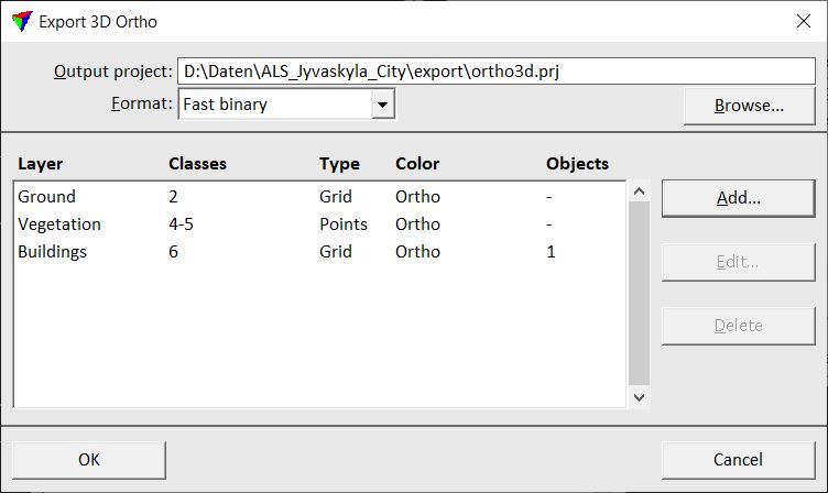
4. Define a storage directory and name for the Output project. The block binary files are stored in the same folder as the project file. Click on the Browse button in order to define the output project in a standard dialog.
5. Select a file format for the block binary files: FastBinary or LAS 1.2.
6. Click on the Add button in order to define rules for the export of different layers, such as ground, vegetation, or buildings.
This opens the 3D Ortho Layer dialog:
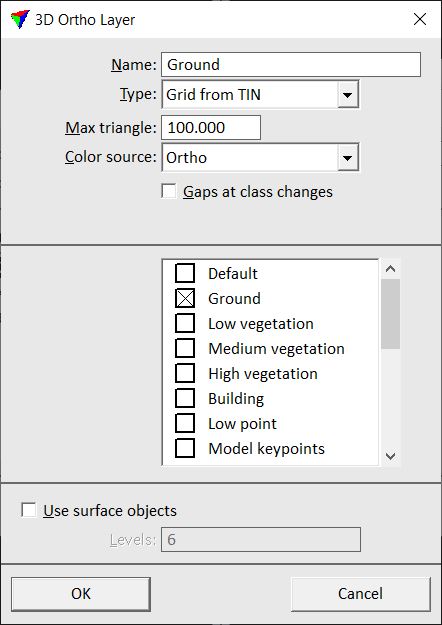
7. Define settings and click OK.
You can Edit and Delete layers by using the corresponding buttons in the Export 3D ortho dialog.
8. Click OK in the Export 3D Ortho dialog.
This starts the point cloud generation process. A progress window displays the progress of the process.
SETTING |
EFFECT |
|---|---|
Name |
Descriptive name of the layer. |
Type |
Defines how points are extracted for the export: •Grid from TIN - a grid is extracted from a TIN created from the laser points. The XY location of a grid point is determined by the pixel center, the elevation by the TIN. •Points directly - the original laser points are exported. |
Max triangle |
Maximum length of a triangle edge in the TIN. Determines how big gaps are filled with points generated by aerial triangulation. This is active only if Type is set to Grid from TIN. |
Color source |
Defines the source for extracting RGB values for the points: •Ortho - each point gets the color of the closest pixel in the orthophotos. •Point color - each point gets the color assigned to laser points. •Fixed color - each point gets a fixed color value. |
Gaps at class changes |
If on, a gap is enforced at boundaries between different classes in the source laser data. This avoids that point are generated by aerial triangulation between different point classes. |
R G B |
RGB color values of a fixed color assigned to points. This is active only if Color source is set to Fixed color. |
List of classes |
Select the source class(es) for this layer. The list contains the active classes in TerraScan. |
User surface objects |
If on, shape elements on the given Levels are used for determining the elevation of exported points inside a shape area. |
The TerraScan project file for the exported point cloud is created with the Color attribute inactive. Therefore, you have to switch the attribute on and save the project before you can see the points displayed by color correctly. See Edit project information for instructions how to edit a project.