

TerraScan User Guide
Draw cloud boundaries
Not UAV
Draw cloud boundaries command draws shape element(s) for area(s) that are covered by the point cloud or by single lines. Single lines are identified by the line number attribute stored for laser points. In addition, the class attribute can be used to further limit the area enclosed by the shape.
The shape elements may be useful to ensure that there are no gaps in the data set or to test if data from specific lines can be removed without causing a gap. The process can draw the shapes on different CAD file levels for each line. This supports the check of line removal without the need to delete the elements.
To draw cloud boundaries:
1. Select Draw cloud boundaries command from the Tools pulldown menu.
This opens the Draw Cloud Boundaries dialog:
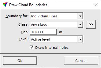
2. Define settings and click OK.
The software checks all blocks of the project and draws the boundary shape(s) into the CAD file. The color of the shape element(s) is determined by the line number (for individual lines) or the active color (for the whole point cloud), line style and weight by the active symbology settings of the CAD platform. After drawing individual line shapes on separate levels, a Bentley design file is compressed automatically.
SETTING |
EFFECT |
|---|---|
Boundary for |
Defines the boundary type: •Whole point cloud - one boundary for the whole project point cloud is drawn. •Individual lines - boundaries for separate lines are drawn. |
Class |
Point class(es) that are included in the shape computation. |
|
Opens the Select classes dialog which contains the list of active classes in TerraScan. You can select multiple source classes from the list that are then used in the Class field. |
Gap |
A new shape element is drawn if there is a gap larger than the given size between points of the same line. |
Level |
CAD file level(s) on which the shape elements are drawn: •Active level - shapes for all lines are drawn on the active level. •Separate levels - shapes for each line are drawn on a separate level. The levels for the shapes are created automatically with the name <LineX> where X is the line number. |
Draw internal holes |
If on, areas within lines without points larger than the given Gap size are enclosed by boundaries. They are defined as holes within the shape element for the line. |
