

TerraScan User Guide
Place Paint Stripes
 Place Paint Stripes tool can be used for the digitization of crosswalk paintings on a road. The tool supports the placement of shapes for the paint lines that form a regular stripe pattern.
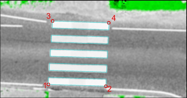
When a stripe pattern is digitized, the user defines the 4 outer corners of the pattern drawing. Then, the software derives the number of paint lines and adjusts them evenly between the outer boundaries. The width of the paint lines is defined in the tool settings. The spacing between the paint lines is slightly adjusted, so it may differ a bit from the definition. The length of the paint lines is defined by the first two data clicks and equal for all shapes. Therefore, if a stripe pattern includes paint lines of different length, you may use the tool several times to place the shapes. The lines of a stripe pattern may also be transversely displaced. Then, the tool derives the displacement from the 4 data clicks defining the corners.
To place a paint stripe drawing:
1. Select the Place Paint Stripes tool.
The Place Paint Stripes dialog opens:
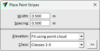
2. Define settings.
3. Define the 4 outer corner points of a paint stripe pattern with data clicks as shown in the sketch above (red circles and number 1-4 indicate the data clicks).
The shape of the paint stripe pattern is displayed at the given location.
4. Place another data click inside the CAD view in order to confirm the paint stripe drawing.
This creates individual shape elements for each paint line of the paint stripe pattern. You can modify the shapes using CAD tools.
SETTING |
EFFECT |
|---|---|
Width |
Width of the paint lines forming the stripe pattern. |
Spacing |
Distance between the paint lines of the stripe pattern. |
Elevation |
Determines how the Z value for the crosswalk drawing is defined: •Mouse click - the current mouse pointer elevation is used. This results in a 2D-like drawing. •Fit using point cloud - a single plane equation is used to fit the crosswalk drawing to the point cloud. This results in a 3D-like drawing. •<surface model> - a single plane equation is used to fit the crosswalk drawing to a surface model loaded in TerraModeler. This results in a 3D-like drawing. |
Class |
Point class(es) from which to derive the elevation of the drawing. This is active only if Elevation is set to Fit using point cloud. |
|
Opens the Select classes dialog which contains the list of active classes in TerraScan. You can select multiple source classes from the list that are then used in the Class field. |
