

TerraPhoto User Guide
Add depth
Add depth command lets you enter a new Depth tie point. Depth tie points are used for deriving trajectory drift corrections in data sets from mobile systems. Therefore, the tie points are collected in TerraPhoto but used in TerraMatch for finding fluctuating corrections. The derived corrections can then be utilized to improve the positioning of images and laser data collected during the same survey.
Depth tie point should be entered at regular distances along roads, railroads, or other linear objects in order to provide a good source for correcting the drift in the trajectory. You may place a tie point, for example, in every 5th or 10th image if the images were captured at a constant driving speed. The point is entered only in those images that see a tie point location best.
Depth tie point require depth maps in the \TEMP directory of the mission. See Compute depth maps for more information.
To enter a new depth point:
1. Select Add depth command from the Point pulldown menu.
The Add common depth point dialog opens:
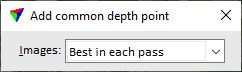
2. Select Images, in which you want to place the tie point: All possible or Best in each pass. The latter option causes that only those images from each drive path are displayed for tie point placement that see the tie point location best.
3. Identify an approximate location with a data click in the Active full view where you intend to enter a Depth point.
The application updates the Active detail view in order to show the selected location.
4. Enter the tie point position with a data click in the Active detail view. You may move or zoom the image in the view in order to find a good tie point location.
The application adds the tie point to the list in the Tie points window. The tie point is defined in the active image.
The tie point pixels in the other images are undefined at this stage. The software selects the next image with an undefined tie point pixel in the list and updates the Secondary detail view in order to show the tie point position.
5. Enter the tie point position with a data click in the Secondary detail view.
The application recomputes the solution point for the tie point and displays the current mismatch for each image. It selects the next image with an undefined tie point pixel in the list and updates the Secondary detail view in order to show the tie point position.
6. Continue with step 5 until all tie point pixels are defined.
7. After entering the last pixel of a tie point, you can continue with step 3 if you want to place the next Depth tie point. Typically, you would select another image before you place the next tie point.
You can check the distribution of tie points along the survey area in another CAD file top view. Make sure that the setting Draw points in all top views is switched on in the Tie point view setup dialog. The dialog is opened by the Setup command from the View pulldown menu. New tie points are displayed in top views after redrawing the view.