

TerraModeler User Guide
Validate Linear Elements
 Validate Linear Elements tool can be used for checking linear elements for geometrical flaws. It is intended to be used, for example, for checking vector data from existing maps (such as building footprints) before it is used for further processing or for validating newly created vector data before delivery.
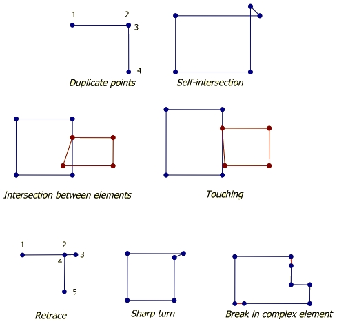
The following figure illustrates the geometrical flaws that can be found with the tool.
The tool opens a dialog with a list of all geometry flaws that it found according to the selected settings. In this dialog, there are user controls for checking the issues in an organized way.
To validate linear elements:
1. Select elements.
2. Select the Validate Linear Elements tool.
This opens the Validate Linear Settings dialog:
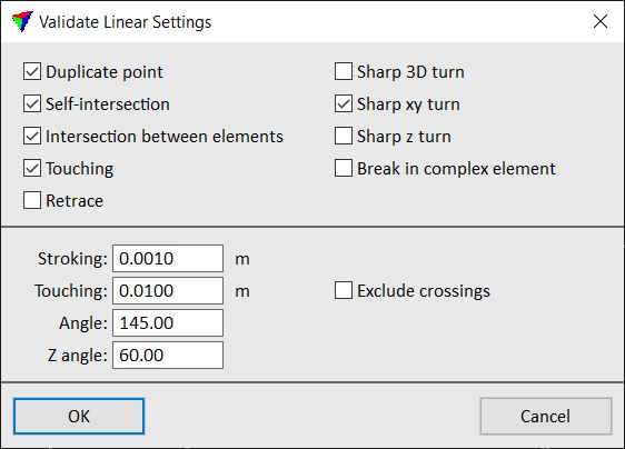
3. Select which geometrical flaws you want to validate.
4. If applicable, define additional settings.
5. Click OK.
This opens the Validate Linear Elements dialog, a dialog that helps you to check the geometrical flaws in the vector data.
Setting |
Effect |
|---|---|
Stroking |
Tolerance distance for checking the geometry. A geometrical flaw is detected if the location of a vertex differs more than the given value from other vertices or lines. |
Touching |
Minimum distance between separate elements. If the distance is smaller, elements are detected as touching elements. |
Angle |
Determines what is a sharp XY turn in the geometry. A value of 145 means that the smallest allowed angle between two lines at a vertex is 35 degrees. Smaller angles are considered a sharp turn. Values can range from 0 to 180. |
z-Angle |
Determines what is a sharp Z turn in the geometry. Defined in the same way as Angle. Values can range from 0 to 180 degree. |
Exclude crossings |
If on, the Touching validity check ignores places where one line string element crosses another line string element at least two times. |
Validate linear elements dialog
The Validate Linear Elements dialog shows a list of geometrical flaws that the tool found in the selected elements. Further, it provides user controls for checking the problems in an organized way. CAD tools can be used to fix the geometry problems.
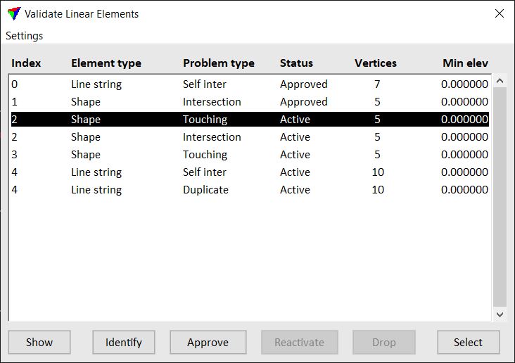
Index - unique ID number of a vector element. One element can have several geometry flaws.
Element type - CAD element type. Valid element types include shapes, complex shapes, ellipses, lines, line strings.
Problem type - geometry flaw.
Status - status of the element. Can be Active, Approved, or Dropped.
Vertices - number of vertices of the element.
Min. elevation - minimum elevation of an element. This column can be changed to show the maximum elevation or the elevation range of vertices of an element.
Show - highlights the selected problem location or element. Select a row in the list and click on the button. Move the mouse pointer inside a CAD file view. This highlights a problem location by drawing small squares around vertices. Place a data click inside a view in order to center the problem location/element in the view.
Identify - selects a problem location or element in the list. Click on the button and place a data click close to an element in a CAD file view. The problem location or element closest to the data click is selected in the list.
Approve - sets the status of a problem element to Approved. This should be used after a geometrical flaw has been fixed.
Reactivate - sets the status of a problem element to Active. The button is only available if an element with status Approved is selected in the list.
Drop - drops a complex element into its single elements. Dropping a complex element is necessary to fix a gap (break). The button is only available if an element with problem type Break and status Active is selected. The status of the dropped element is changed to Dropped.
Select - selects the geometry of the element that is selected in the list. Select a row in the list and click on the button. This selects the element. You may use the Show button in order to move the view to the location of the element.
Processing settings command in the Settings pulldown menu lets you view and change the settings for validating elements. The command opens the Validate linear elements processing dialog described above. After changing settings, the list of elements in the Validate linear elements dialog is updated automatically.
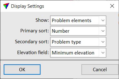
View settings command in the Settings pulldown menu define the content and order of elements in the Validate linear elements dialog.
Setting |
Effect |
|---|---|
Show |
Determines what elements are displayed in the list: All elements or Problem elements. |
Primary sort |
The elements are sorted primarily according to the given attribute. |
Secondary sort |
The elements are sorted secondarily according to the given attribute. |
For elevation show |
Determines what vertex elevation value is shown in the last column of the list: Minimum elevation, Maximum elevation or Elevation change. |