

TerraModeler User Guide
Creating a design surface
 TerraModeler can be used to create design surfaces for earthworks projects. The best approach is to first create graphical elements representing the shape of the design surface. This is exactly what you did in the previous step with the Calculate Slope tool. You can now use the green shape element and the yellow slope element to create a new design surface.
To create a design surface:
1. Select the elements in View 4.
Your selection set should include the green shape element and the yellow line string representing the upper slope edge.
2. Select Insert Breakline Element tool from the Create Surfaces toolbox.
This opens the Insert Breakline Element dialog:
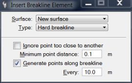
3. Select New surface as the Surface to insert points into and Type as Hard breakline .
4. Switch Generate points along breakline on and enter 10.0 into the Every field.
This setting generates new points along a long breakline if the distance between two breakline points is longer than 10 meters.
5. Accept the elements.
This opens the Triangulate surface dialog.
6. Accept default settings by clicking OK which opens the Surface settings dialog:
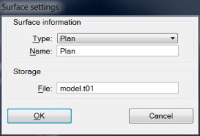
7. Select Plan in the Type field.
8. Enter Plan as the surface Name.
9. Click OK.
TerraModeler creates a new surface using the vertices of the selected elements.