TerraModeler User Guide
Breakline types
TerraModeler knows the following breakline types which are closely related to the Point Types of the TIN format:
Breakline type |
description |
typical examples |
Random point |
Randomly distributed point elements. |
Surveyed point features, thinned ground points from a point cloud, model keypoints.
|
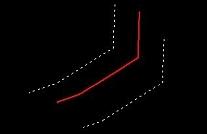
Hard breakline |
3D line element that represents a sharp edge in a surface. Vertices of the line element are added to the TIN and thus, effect the TIN structure. |
Edges of hard surfaces, sharp terrain slope edges.
|
Soft breakline |
3D line element that represents a smooth edge in a surface. Vertices of the line element are added to the TIN and thus, effect the TIN structure. |
Smooth, "round" terrain slope edges.
|
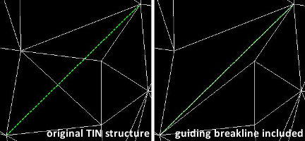
Guiding breakline |
2D line element that forces triangle edges to follow its direction. No additional vertices are added to the TIN from this type of breakline. |
Quick solution for approximate terrain slope edges.
|
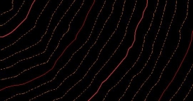
Contour |
3D contour line element. |
Common contour lines that represent the ground surface.
|
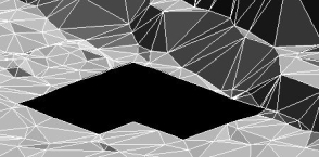
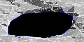
2D hole |
2D shape element that represents void areas ("gaps") in a surface model. The elevation along the boundary is determined by the closest elevation next to the polygon boundary. In the TIN file format specification, this is referred to as "inner boundary". |
Building footprints.
|
3D hole |
3D shape element that represents void areas ("gaps") in a surface model. The elevation along the boundary is determined by the elevation of the polygon boundary. In the TIN file format specification, this is referred to as "inner boundary". |
Water boundaries.
|
2D boundary |
2D shape element representing the outer boundary of a surface model. Areas outside of the boundary are invalid and not part of the surface model. The elevation along the boundary is determined by the closest elevation next to the shape boundary. |
A surface model should have only one outer boundary. |
3D boundary |
3D shape element representing the outer boundary of a surface model. Areas outside of the boundary are invalid and not part of the surface model. The elevation along the boundary is determined by the elevation of the shape boundary. |
A surface model should have only one outer boundary. |