

TerraModeler User Guide
Connect Linear Elements
 Connect Linear Elements tool creates a continuous line string from two or more single line (string) elements. The line string creation considers the XY and Z coordinates of the vertices of the original line elements. The new line string is created on the active CAD file level using the active symbology settings.
The tool can be used, for example, to create a continuous line from separate line elements that were extracted automatically, such as paint markings extracted from mobile laser scanner data in TerraScan.
To connect linear elements:
1. Select line elements.
2. Select the Connect Linear Elements tool.
This opens the Connect Linear Elements dialog:
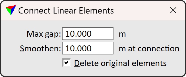
3. Define settings.
4. Place a data click inside a CAD file view in order to accept the line string creation.
This draws the new line string into the CAD file.
Setting |
Effect |
|---|---|
Max gap |
Maximum gap between two adjacent line elements that is closed by the tool. Measured as true 3D distance between vertices. |
Smoothen |
Determines the level of smoothing in XY and Z applied to the new line string. The larger the value, the more smoothing is applied. |
Delete original elements |
If on, the original segments are removed when the continuous line is created. |
Each data click inside a CAD file view creates a new line string from the selected elements as long as the tool is active. This may lead easily to duplicated lines created from the same selection set. You can undo the creation of the new line string by using the Undo command from the Edit pulldown menu of the CAD platform.