

TerraModeler User Guide
Alignment Offset
 Alignment Offset tool provides an easy way to place elements at a specific station or at a specific 3D offset from an alignment element. The tool can use any linear element as the alignment.
Alignment Offset tool opens a dialog which dynamically displays station and offset values at the mouse pointer location. You can lock data points by station, offset, elevation difference, or gradient from the selected alignment.
General procedure for applying alignment locks:
1. Select the Alignment Offset tool.
2. Identify the alignment element.
3. Accept the element.
This opens the Alignment Offset dialog:
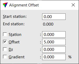
4. Switch on the locks which you want to apply.
5. Select any CAD element placement tool you want to use.
When you enter a data point, its coordinates are adjusted according to the alignment offset locks and related to the selected alignment element.
Setting |
Effect |
|---|---|
Start station |
Station value for the start point of the alignment. Default is zero. |
Station |
If on, the XY location of a data point is adjusted to the given station position. |
Offset |
If on, the XY location of a data point is adjusted to the given offset from the alignment. The data point determines whether the offset is computed to the left or to the right of the alignment. |
Dz |
If on, the Z value of a data point is adjusted by adding this elevation difference to the elevation of the alignment element. |
Gradient |
If on, the Z value of a data point is adjusted by using this gradient percentage from the elevation of the alignment element. |
Make sure to turn off Alignment Offset locks if you do not need it any longer. As it effects all data points, it may interfere with your normal work. The lock is turned off when the Alignment Offset dialog is closed.