

TerraScan User Guide
Adjust to geoid
Adjust to geoid command applies an elevation correction to trajectory files. The command is used, for example, to transform the WGS84-based ellipsoidal elevation values of a raw trajectory file to a local height model. TerraScan implements a number of national, continental or global geoid models. The corresponding files are provided with the installation of a bundle package (Terrasolid installation bundle for Spatix or Bentley CAD) and stored in the \GEOID folder of the Terra installation directory.
Alternatively, the input model for geoid adjustment must be provided in one of the following formats:
•Points from file - text file containing space-delimited X Y dZ- points.
•TerraModeler surface - triangulated surface model created from X Y dZ - points. The surface model in TerraModeler has the advantage that you can visualize the shape of the adjustment model.
•Selected linear chain - linear element of which the vertices represent the X Y dZ - points.
XY are the easting and northing coordinates of the geoid model points, dZ is the elevation difference between ellipsoidal and local heights at the location of each geoid model point. Intermediate adjustment values of the model are derived by aerial (text file or surface model as input) or linear (linear element as input) interpolation between the known geoid model points.
You can find more detailed information about elevation adjustment in Section Geoid adjustment.
To adjust trajectories to a geoid model:
1. (Optional) Load a geoid model into TerraModeler.
2. (Optional) Select trajectory file(s) to adjust.
3. Select Adjust to geoid command from the Tools pulldown menu.
This opens the Adjust Trajectories to Geoid dialog:
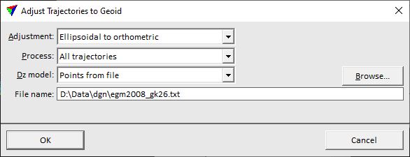
4. Define settings and click OK.
This applies the elevation adjustment to all or selected trajectories. The modification is saved to the trajectory binary files in the active trajectory directory. An information dialog shows the minimum and maximum values of the adjustment.
SETTING |
EFFECT |
|---|---|
Adjustment |
Direction of the elevation adjustment: •Ellipsoidal to orthometric - adjustment from ellipsoidal to orthometric height values. This is the normal way of an geoid adjustment. •Orthometric to ellipsoidal - adjustment from orthometric to ellipsoidal height values. This is the reverse way of an geoid adjustment. |
Process |
Trajectories to adjust: •All trajectories - all trajectories in the list. •Selected only - selected trajectories only. |
Dz model |
Source file that provides the geoid correction model: •Points from file - space separated X Y dZ text file as described in Introduction to geoid adjustment. •ISG geoid file - a geoid file in isg format. •Selected linear chain - linear element selected in the CAD file. •<name> - name of a geoid model loaded as surface in TerraModeler. •<implemented model> - name of an implemented geoid model. |
File name |
Name of the geoid text file. This is active only if Dz model is set to Points from file. |
Extend |
Distance from a selected linear element by which the linear chain is extended for elevation value corrections. This is active only if Dz model is set to Selected linear chain. |
Projection |
Projection system of the geoid model. This is active only if Dz model is set to any implemented geoid model. |