

TerraScan User Guide
Draw boundaries
Not UAV
Draw boundaries command draws the boundaries and (optional) names of block definitions into the CAD file. This can be used, for example, to draw boundaries if points have been imported into the project without defining block boundaries beforehand or after blocks have been transformed.
The command can also be used to draw the outer boundary of a project area into the CAD file.
To draw block boundaries into the CAD file:
1. (Optional) Select block definitions in the Project window to be drawn into the CAD file.
2. Select Draw boundaries command from the Block pulldown menu.
This opens the Draw Block Boundaries dialog:
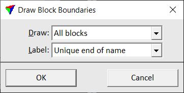
3. Select settings and click OK.
The boundaries and, if selected, block labels are drawn as shape and text elements into the CAD file. The elements are drawn on the active level using the active symbology settings of the CAD platform.
SETTING |
EFFECT |
|---|---|
Draw |
Boundaries to be drawn: All blocks, Selected blocks, or Project outer boundaries. |
Label |
Defines the way of labeling the blocks: •None - no text elements are created. •Block number - the complete block number is drawn. •Full file name - the complete file name without extension is drawn. •Unique end of name - only the last unique number or text string of the block names is drawn. This works only if more than one block is drawn into the CAD file. This is active only if Draw is set to All blocks or Selected. |