

TerraScan User Guide
Write section points
Not Lite
Write section points action produces new files that contain only points of cross sections at regular steps along an alignment element. The resulting files are suitable for visualizing data of a corridor object, such as a road or railroad.
The action relies on a linear element that is used as alignment element. The parameters of the action determine, how many points are written in the new files by settings like the width of the sections left and right of the alignment element, the step size along the alignment element, and the depth of the sections.
The output files can be written with either the original coordinates of the points or in an artificial coordinate system Station-Offset-Z. The artificial coordinate system is defined by:
•X = scaled station along the alignment element.
•Y = offset to the left and right sides of the alignment element.
•Z = scaled elevation values.
The artificial coordinate system should be used, for example, to produce a data set suited for digitization tasks along a corridor data set. The advantages are:
•faster viewing as the corridor is shortened.
•exaggerated elevation values make small elevation changes better visible.
•easier panning as the whole corridor runs along the view’s X axis without curves.
•better shaded surface display as the direction of the corridor relative to the light source does not change.
You must select the alignment element before starting a macro with the Write section points action.
SETTING |
EFFECT |
|---|---|
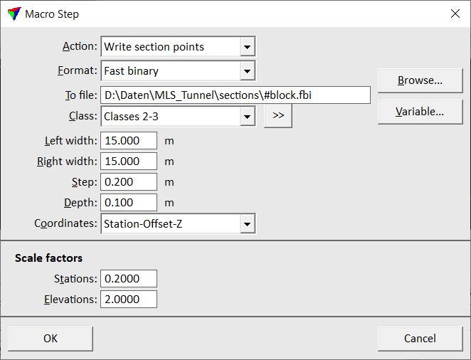
Format |
File format of the output files: FastBinary, LAS, Scan binary 8 bit or 16 bit. |
To file |
Storage location and name of the output file(s). If there should be individual output files for several block binary files, the file name must include a Variable. Add the extension of the output file manually at the end of the file name according to the selected output Format. |
Variable |
Opens the Macro variable dialog which contains the list of variables. Select the variable that you want to use as part of the output file name. |
Class |
Point class(es) that are included in the output file(s). |
|
Opens the Select classes dialog which contains the list of active classes in TerraScan. You can select multiple source classes from the list that are then used in the Class field. |
Left width |
Width of the cross sections to the left side of the alignment element. The side is relative to the digitization direction of the alignment. |
Right width |
Width of the cross sections to the right side of the alignment element. The side is relative to the digitization direction of the alignment. |
Step |
Distance between consecutive cross sections along the alignment element. |
Depth |
Depth of a cross section. |
Coordinates |
Defines the coordinate system of the output files: Original or Station-Offset-Z. |
Stations |
Scale factor for stations along the alignment element. Determines the compression of the original corridor length. This is active only if Coordinates is set to Station-Offset-Z. |
Elevations |
Scale factor for elevation values. Determines the elevation exaggeration. This is active only if Coordinates is set to Station-Offset-Z. |

Return value: Number of points written into the output file or -1 if the process failed.