

TerraPhoto User Guide
Definition of target vectors
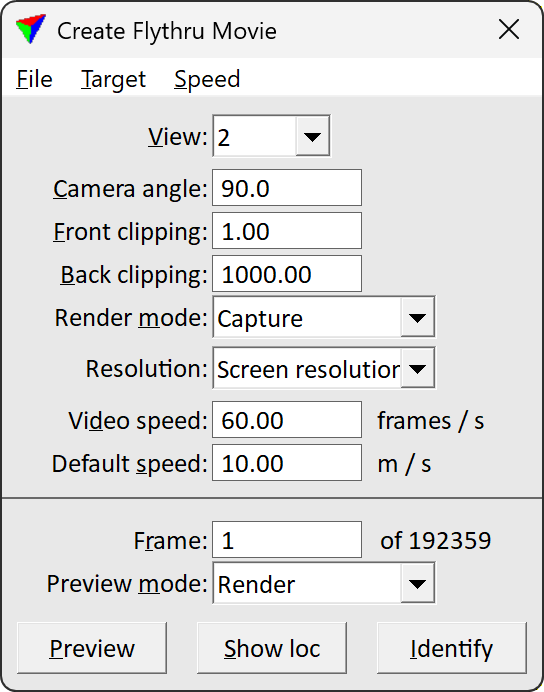
Target vectors determine the viewing direction and distance of the camera from the camera path to the target. They are attached as line elements to the camera path using tools from the Create Flythru Movie dialog:
To define target vectors:
1. Select Create vectors command from the Target pulldown menu in the Create Flythru Movie dialog.
This opens the Create target vectors dialog:
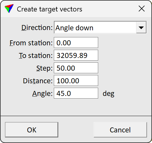
2. Define settings and click OK. If direction is set to Fixed point , the target point has to be defined by a data click inside a view.
This attaches the vectors to the camera path. The result can be checked by rotating the view.
3. (Optional) Besides using the predefined settings, target vectors can be modified manually using, for example, Modify Element tools of the CAD platform. Manual modifications need to be updated by using Update from design command from the Target pulldown menu in the Create Flythru Movie dialog.
SETTING |
EFFECT |
|---|---|
Direction |
Camera viewing direction: •Fixed point - the camera is directed towards one point during the whole flythru. •Forward onto surface - the camera is directed forward towards a surface model loaded in TerraModeler. •Forward horizontal - the camera is directed in a forward horizontal direction independently of the camera path direction. •Forward - the camera is directed in a forward direction relative to the camera path. •Angle down - the camera is directed down at a specific Angle. |
From station |
First location of a target vector along the camera path. |
To station |
Last possible location of a target vector along the camera path. |
Step |
Distance between two target vectors along the camera path. Determines the distance between camera direction changes. This is only active if Direction is not set to Fixed point. |
Distance |
Length of a target vector. This is only active if Direction is not set to Fixed point. |
Surface |
Surface model used as reference. This is only active if Direction is set to Forward onto surface. |
Dz |
Vertical elevation difference between the reference surface and the target vector’s end point. This is only active if Direction is set to Forward onto surface. |
Angle |
Angle off from horizontal by which the camera is looking down. This is only active if Direction is set to Angle down. |
The automatic placement of target vectors can be undone be using the CAD platform Undo command. Existing target vectors are replaced by choosing another setting for direction in the Create target vector dialog as long as they are not manually modified.
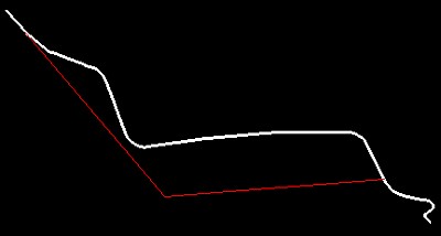
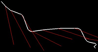
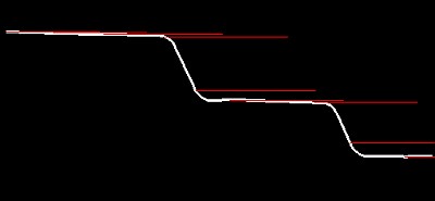
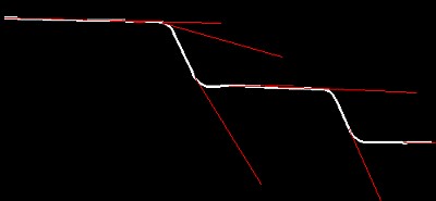
The following figures illustrate the differences of direction settings provided by the tool. The white line is the camera path and the red lines are the target vectors in 3D perspective views.
Fixed point |
Forward onto surface |
Forward horizontal |
Forward |
To view the current target vector settings:
1. Select View list command from the Target pulldown menu in the Create Flythru Movie dialog.
This opens the View target vectors information window:
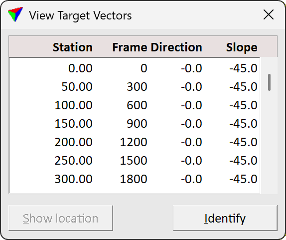
The window shows a list of all stations along the camera path, and for each station the frame number, the direction, and the slope of the target vectors.
To show the location of a vector, select a line in the View target vectors window. Select Show location and move the mouse pointer into a view. This highlights the selected target vector.
To identify a vector, select Identify and click next to a vector in a view. This selects the corresponding line in the View target vectors window.