

TerraPhoto User Guide
Draw locations
Draw locations command draws the location of images into the CAD file. The location may be represented by just a marker of the camera position, a footprint polygon, or a drawing of the image projection.
The tool may be useful for the following tasks:
•To locate places where there is redundant imagery caused by multiple overlapping lines.
•To locate gaps between images. This can be easily seen if footprint polygons are displayed as filled shapes.
•To identify images that do not have enough tie points. The tie point value that is required for a well-defined image is set in Tie points / Display category of the TerraPhoto Settings.
•To locate images that belong to the same group or line.
To draw image footprints:
1. Select Draw locations command from the Utility pulldown menu.
This opens the Draw locations dialog:
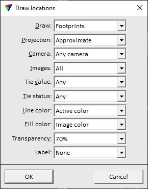
2. Select settings and click OK.
This draws the image location on the active level using the given color settings.
SETTING |
EFFECT |
Draw |
Determines how image locations are drawn: •Location marker - a rectangle is drawn at the camera position of an image. This is always applicable, also if no ground model is available. •Footprints - draws a shape that shows the area covered by the image on the rectification surface, usually the ground. This requires a ground model loaded in TerraPhoto. •Projections - draws the footprint of an image and line elements connecting the image corners on the ground with the camera position. This requires a ground model loaded in TerraPhoto. |
Size |
Length of the longer edge of a rectangular image location marker. The length of the shorter edge is derived based on the image size. This is only active if Draw is set to Location marker. |
Projection |
Accuracy of a footprint shape to draw: •Approximate - uses ground elevation only at the camera xy location. The shape is drawn assuming that the ground is flat. •Accurate - computes ground elevation at several locations along the image edges and produces a more accurate shape. This is only active if Draw is set to Footprints. |
Camera |
Name of the camera of which image locations are drawn. Alternatively, image locations from Any camera can be drawn. |
Draw images |
Defines which image locations are drawn related to selection and rectify status: •All - all images. •Selected - images selected in the active image list. •Active - images with rectification status Rectify . •Inactive - images with rectification status No Rect. |
Tie value |
Defines which image locations are drawn related to the tie point value of the images: •Any - all images. •Well defined - draws images with a tie point value equal or larger than the value defined in TerraPhoto Settings. •Under defined - draws images with a tie point value smaller than the value defined in TerraPhoto Settings. The options Well defined and Under defined are only active if tie points are loaded in TerraPhoto. |
Tie status |
Defines which image locations are drawn related to the tie point status of the images: •Any - all images. •Check - draws images with tie point status Check. •Approve - draws images with tie point status Approved. The options Check and Approve are only active if tie points are loaded in TerraPhoto. |
Line color |
Line color of the image location drawing: •Active color - images inside the rectification surface are drawn with the active color of the CAD file, images outside the rectification surface are drawn with red (or blue) color. •Group color - images are drawn using different colors according to assigned group numbers. The group number determines the color by using the same color number from the active color table of the CAD file. •Image color - display color stored for each image in the image list. •Line color - images are drawn using different colors according to assigned line numbers. The line number determines the color by using the same color number from the active color table of the CAD file. •Mismatch distance - images are drawn according to the mismatch computed from tie points. This is only active if tie points are loaded in TerraPhoto. |
Fill color |
Fill color of the image location drawing: •None - no fill color, only the outline is drawn. •Active color - images inside the rectification surface are drawn with the active color of the CAD file, images outside the rectification surface are drawn with red (or blue) color. •Group color - images are drawn using different colors according to assigned group numbers. The group number determines the color by using the same color number from the active color table of the CAD file. •Image color - display color stored for each image in the image list. •Line color - images are drawn using different colors according to assigned line numbers. The line number determines the color by using the same color number from the active color table of the CAD file. •Mismatch distance - images are drawn according to the mismatch computed from tie points. This is only active if tie points are loaded in TerraPhoto. |
Transparency |
Transparency level of the image location drawing. Bentley CAD only |
Label |
Text element that is drawn for each image location: •None - no label is drawn. •Image number - the unique image number. •Full file name - the full name of the image. |