

TerraModeler User Guide
Export / Graphical elements
Graphical elements command draws different types of surface model points and lines on given levels into the CAD file. Random and inferred points can be drawn as leveling text elements, as zero length lines (points), or as X character text elements. Breaklines, contours, hole boundaries, and outer boundaries are drawn as linear elements.
The text design of the leveling text elements for random and inferred points are defined in Elevation labels category of the TerraModeler Settings.
To draw surface model elements into the CAD file
1. Select Graphical elements command from the File / Export pulldown menu.
This opens the Export Graphical Elements dialog:
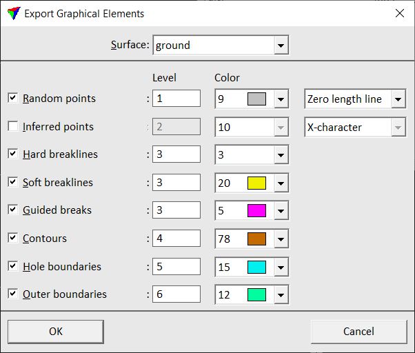
2. Select a Surface model for which to draw elements into the CAD file.
3. Select the surface element to be drawn and define Level and Color settings.
4. Define the element type for drawing random and inferred points.
5. Click OK.
This draws the selected elements into the CAD file.
The command may be useful if you want to modify the surface in a way TerraModeler does not provide any suitable tools for. For example, TerraModeler does not include a tool for shifting a group of surface model elements horizontally. You can accomplish this by:
1. Export the surface model elements as graphical elements into the CAD file.
2. Switch off all other levels in a view.
3. Move the graphical elements using CAD tools.
4. Delete the old surface model.
5. Use Triangulate View tool to create a new surface model from the shifted graphical elements.