

TerraModeler User Guide
Triangulate View
 Triangulate View tool creates a surface model from graphical elements displayed in a view. This tool uses only elements residing on levels visible in the selected view and located inside the view range.
This tool includes closed elements as breakline points or holes, linear elements as breakline or contour points, and single point elements as random points into a surface model.
You can use this tool to create a new surface model or to add points to an existing model loaded in TerraModeler.
To triangulate view elements:
1. Select the Triangulate View tool.
This opens the Triangulate View dialog:
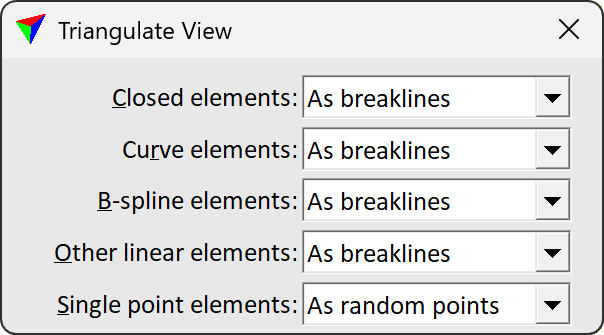
2. Identify the view to triangulate by a mouse click inside the view.
This opens the Triangulate surface dialog. Follow the common steps for Creating a surface model.
The software creates the surface model from elements that are visible in the selected view.
Setting |
Effect |
|---|---|
Closed elements |
How to use closed elements: As breaklines , As 3D holes or As 2D holes. |
Curve elements |
How to use curve elements: As breaklines or As contours. |
B-spline elements |
How to use B-splines: As breaklines or As contours. |
Other linear elements |
Other linear elements are always used as breaklines. |
Single point elements |
Single point elements are always used as random points. |
Scan reference files |
If on, elements in reference files that are attached to the active CAD file are used for surface creation as well. |