

TerraModeler User Guide
Display Drainage
Not Lite
 Display Drainage tool computes and displays the flow of drainage water on a surface model. It uses a grid-based approach to determine the water flow.
The process starts by placing an imaginary rain drop at each grid cell. Then the software determines where that rain drop would travel. It compares the elevation of the cell center point with the elevation of each of the neighboring cells. If a lower elevation is found, the rain drop travels to the neighboring cell to which the slope is steepest. This process continues until each of the rain drops have reached a pit or a local minimum elevation point.
Display Drainage tool creates CAD file elements which are not linked to a surface model. Thus, TerraModeler is not able to update or erase elements created by this tool.
To display drainage:
1. Select the Display Drainage tool.
The Display Drainage dialog opens:
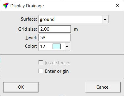
2. Define settings and click OK.
3. If Enter origin is switched on, define the origin point of a drainage grid cell with a data point.
This computes the drainage water flow and displays the results temporarily in all open views. The display is updated every time when the view contents is updated with the corresponding CAD tool.
In addition, the Drainage Detail dialog opens for Viewing the drainage system in detail.
Setting |
Effect |
|---|---|
Surface |
Name of the effected surface model. |
Grid size |
Size of the grid cells for drainage computation. |
Level |
Number of the level in the CAD file on which the drainage network is drawn if it is drawn permanently into the CAD file. |
Color |
Color of the lines and arrows the represent the water flow. Uses the CAD file color table. |
Inside fence |
If on, the drainage system is only displayed inside a fence. This is only active if a polygon has been selected or a fence has been drawn before the tool is started. |
Enter origin |
If on, you can enter the origin point of a drainage grid cell with another data point. |
Viewing the drainage system in detail
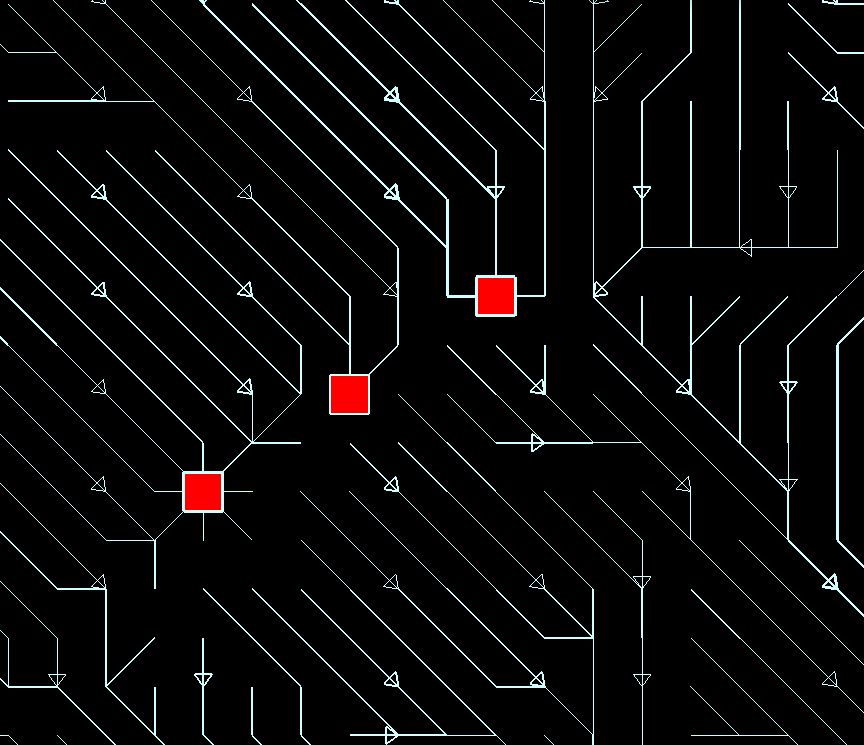
The drainage display shows the paths that rain drops would travel according to the grid-based calculation. The arrows show the flow direction and the line width gives an indication on how many rain drops travel along a path. Red squares mark places where drainage water would gather (outlet, pour point). As the rain drops can not travel outside the surface model, there may be several squares at the outer edges of the model.
The Drainage Detail dialog allows you to control the level of detail in the drainage display.

When the slider is set to High, the drainage display shows the paths of each single rain drop. If you move the slider closer to Low, the software leaves out smaller streams and only displays the major paths. The drainage network remains visible as long as you keep the Drainage Detail dialog open.
In addition, the Show area button in the Drainage Detail dialog can be used to identify the runoff area for a selected drainage grid cell.
Click on the Write to design button in order to draw the drainage display permanently into the CAD file.
To view a runoff area:
1. Click on the Show area button in the Drainage Detail dialog.
2. Move the mouse inside a view.
The size of the Runoff area for the grid square at the mouse pointer location is displayed in the Drainage Detail dialog. This is the combined surface area of all the squares from which a rain drop travels to or through the selected grid cell.
3. (Optional) Enter a data point in order to display the boundaries of the runoff area.
This draws the runoff area as a shape element into the CAD file using the active symbology.