

TerraMatch User Guide
Find Mirror Angle Correction
 Find Mirror Angle Correction tool solves point cloud corrections dependent on scan angle. The tool can adjust points in a cross section perpendicular to system direction of travel, thus making it useful to fix smiling face error present in point cloud data. Corrections are solved individually per scanner.
Finding mirror angle corrections requires laser data from overlapping strips or scanners and preferably from a hard surface, such as a road surface. The points on the surface must be classified into a separate class. In addition, trajectories with timestamps covering the point cloud are required. The correction is computed per scanner by comparing mismatch to surfaces observed by other scanners and strips.
The tool provides correction values for angle intervals in a TerraMatch correction file. This correction file can then be used to apply the corrections to the laser data of a project. There is also an option of smoothing the correction values. Alternatively, corrections can be applied directly from the tool to loaded points.
To find mirror angle correction:
1. Load laser data into TerraScan from an area that is suitable for finding mirror angle corrections.
2. Select the Find Mirror Angle Correction tool.
This opens the Find Mirror Angle Correction dialog:
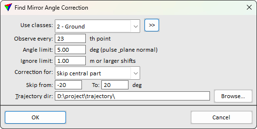
3. Define settings and click OK.
Setting |
Effect |
|---|---|
Use classes |
Classes to use for finding mirror angle corrections. |
Observe every |
How many points to make an observation with. Use to limit point usage with high density clouds. |
Angle limit |
Limit for how much normal vector of the local plane has to differ from vector from the location to the scanner. The purpose of this setting is to eliminate observations where plane normal vector and the vector to the scanner are parallel, which means that mirror angle shift will not result in any change on the surface. |
Ignore limit |
Limit value for differences between strips that the software tries to match. The values should be a bit higher than the largest mismatch between strips. Larger mismatches are treated as gross errors and therefore not included in the calculation. |
Correction for |
If set to Skip central part, any adjustment does not apply to points within specified scan angle range. |
Skip from |
Lower and upper limit for angle range not adjusted. This is only available if Correction for is set to Skip central part. |
Trajectory dir |
Directory containing TerraScan trajectory files. |
This opens the Mirror Angle Result dialog:
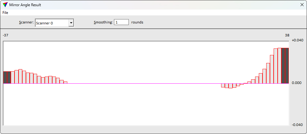
4. Adjust the level of smoothing.
Setting |
Effect |
|---|---|
Scanner |
Number of the scanner for which to apply intensity correction values. |
Smoothing |
Number of smoothing rounds to apply to the correction curve. |
File / Save correction |
Saves a TerraMatch correction file for being used in the Apply Correction tool. |
File / Apply correction |
Apply correction to loaded points. |
5. Save the corrections using the Save corrections command from the File pulldown menu.
6. Close the Mirror Angle Result dialog.
7. Apply the range corrections to laser data using the Apply Correction tool.