Compute distance
Compute distance command computes a distance value for points. The distance can be computed based on several references:
•3D vector elements in the CAD file, such as planar shapes, linear elements or surface elements.
•the closest overlapping line in a point cloud.
•the average between overlapping lines.
•ground class(es) or other class(es).
•any surface model loaded in TerraModeler.
•powerline wires that have been produced with the Detect wires tool.
•range which is the distance to the scanner position at the moment of time when a point was captured. This requires trajectory information available in TerraScan.
•built-in vegetation indexes Normalized and Visual band differences. This requires true-color (Visual band difference) and additionally infra-red color information (Normalized difference) stored for the points. The distance value expresses how likely a point belongs to vegetation (larger positive value) or not (larger negative value). Distance values range between -1 and +1. The vegetation index distance values may support the ground classification of photogrammetric point clouds.
•Riegl Extra Byte attributes such as Echo length (= Pulse width) and Deviation (= Pulse shape deviation). The attribute values are translated into a distance value which indicates how likely a point belongs to a hard surface (ground) or not. The distance values range between -1 and +1, values between -1 and 0 are considered to represent ground. The higher the value, the less likely a point represents ground. The distance values may support the ground classification of LiDAR point clouds captured with Riegl scanners.
•a longitudinal section line in order to detect road bumps and potholes. The trajectories of an MLS survey or any other road center line element may be drawn in the CAD file in order to be used as reference element. The laser data should be classified into hard surface and noise on asphalt up to maximum 1 cm above/below hard surface. The reference element provides the direction of the road. In the computation process, a line equation is fitted to a longitudinal slice of data with a given length and depth. Points above the fitted line get a positive distance value and represent bumps, points below the fitted line get a negative distance value and represent potholes. Use distance coloring with e.g. +-15 cm distance values in order to illustrate road damage.
The distance value can be used for visualization of points and for further processing steps. The following processing commands rely on a distance computed from ground:
•Classify by distance / Classify groups by distance
•Assign groups and corresponding macro action
•Classify groups by best match
The distance value can be stored in TerraScan FastBinary files. In addition, image files can be created from loaded points by using the distance attribute of points in order to display the information in other software products.
To compute distance values:
1. If you want to compute distance values for road bumps and potholes, select the vector elements that represent these road damages.
2. Select Compute distance command from the Tools pulldown menu.
This opens the Compute Distance dialog:
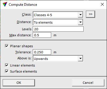
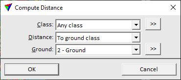
The Distance setting determines which additional settings are available in the dialog.
2. Define settings and click OK.
This computes the distance values. An information dialog shows the number of effected points when the process is finished.
SETTING |
EFFECT |
|---|---|
Class |
Point class(es) for which dimensions and normal vectors are computed. |
|
Opens the Select classes dialog which contains the list of active classes in TerraScan. You can select multiple source classes from the list that are then used in the Class field. |
Distance |
Method for computing the distance: •To elements - distance between a point and vector elements drawn in the CAD file. •To closest line 3D - 3D distance between a point and its closest neighbour point. The computation takes the normal vector direction of points into account. •To closest line dz - vertical distance between a point and its closest neighbour point in XY of another line. •To line average Z - vertical distance from a point to the average elevation between overlapping lines. The computation is based on TINs created from points of one line. •To ground class - vertical distance from a point to the ground class(es). A temporary TIN is created from points in the ground class(es) in order to compute the distance. •To another class - vertical distance from a point to points in the given Other class. •To wires - distance from a point to the closest powerline wire. Line strings for wires must be produced with the Detect wires tool. •<TIN> - distance from a point to a surface model loaded in TerraModeler. •Range 3D - 3D distance from the scanner position to a point. •Range xy - horizontal distance from the scanner position to a point. •Range offset - left/right distance from the scanner position to a point. •Range forward - forward/backward distance from the scanner position to a point. •Range dz - vertical distance from the scanner position to a point. •Normalized difference - built-in vegetation index. •Visual band difference - built-in vegetation index. •Echo Length - Riegl Extra Byte attribute Pulse width. •Deviation - Riegl Extra Byte attribute Pulse shape deviation. •Road bumps & potholes - distance to longitudinal section line. |
Levels |
Numbers of CAD file levels on which the elements are drawn. Level ranges and several levels can be define with minus and comma, for example: 1-5,10,22. This is only active if Distance is set to Elements. |
Max distance |
Maximum distance of points from elements for which a distance value is computed. This is only active if Distance is set to Elements. |
Planar shapes |
If on, planar shapes are considered as reference elements. This is only active if Distance is set to Elements. |
Tolerance |
Defines a stroking tolerance for curved element types. This determines what shapes are considered as planar. This is only active if Distance is set to Elements and Planar shapes is switched on. |
Above is |
Defines which direction is considered as positive distance from planar shapes: •Upwards - points above a shape. •Clockwise side - points in clockwise direction of a shape. This is only active if Distance is set to Elements and Planar shapes is switched on. |
Linear elements |
If on, linear elements are used for computing a distance. This is only active if Distance is set to Elements. |
Surface elements |
If on, surface elements are used for computing a distance. This is only active if Distance is set to Elements. |
Max distance |
Maximum distance between overlapping lines for which a distance value is computed. This is only active if Distance is set to Closest line 3D or Closest line dz. |
Ground |
Point class(es) used as reference ground level. This is only active if Distance is set to Ground class. |
|
Opens the Select classes dialog which contains the list of active classes in TerraScan. You can select multiple source classes from the list that are then used in the Ground field. This is only active if Distance is set to Ground class. |
Other class |
Point class(es) used as reference class(es). This is only active if Distance is set to Another class. |
|
Opens the Select classes dialog which contains the list of active classes in TerraScan. You can select multiple source classes from the list that are then used in the Other class field. This is only active if Distance is set to Another class. |
Max distance |
Maximum distance between a point and reference points in another class. The distance value is not stored for a point if it is larger than the given maximum value. This is only active if Distance is set to Another class. |
Wire levels |
Number(s) of CAD file level(s) on which powerline wires are drawn. Several level number can be separated by comma, a range of level numbers can be defined by a minus sign, for example 10,14,22 or 3-5. This is only active if Distance is set to Wires. |
Find using |
Distance definition: •Vertical distance to wire - vertical distance from a wire. •3D distance to wire - 3D distance from a wire. •Falling tree logic - each point is considered as the tip of a tree with its trunk at the xy location of the point and the elevation of the base point on the ground. The shortest distance of the point “falling like a tree” to a wire is computed. This is only active if Distance is set to Wires. |
Within offset |
Maximum horizontal distance from a wire within which a distance value is computed. Basically, this value defines the corridor left and right of the wires for computing distance values. This is only active if Distance is set to Wires. |
Ground |
Point class(es) used as ground level. This is only active if Distance is set to Wires and Find using to Fallen tree logic. |
Limit |
Threshold value that separates vegetation from non-vegetation by using a vegetation index. This is only active if Distance is set to Normalized difference or Visual band difference. |
Neutral length |
Echo length/Deviation value that is translated into a distance value of 0. This is only active if Distance is set to Echo length or Deviation. |
Spread |
Echo length/Deviation value that is translated into the minimum and maximum distance value of ±1. This is only active if Distance is set to Echo length or Deviation. |
Max offset |
Maximum horizontal distance of a point from the longitudinal section line. Only point within the given offset are considered in the distance computation. This is only active if Distance is set to Road bumps & potholes. |
Fit length |
Length of a longitudinal slice of data used for fitting a line equation for each point. Together with the Fit depth value it determines, how big damages can be detected. This should be bigger than the largest bump/pothole to find. If the value is too small, bigger damages may be missed. If the value is too big, smaller details of damages may be missed. This is only active if Distance is set to Road bumps & potholes. |
Fit depth |
Depth of a longitudinal slice of data used for fitting a line equation for each point. Together with the Fit length value it determines, how big damages can be detected. This is only active if Distance is set to Road bumps & potholes. |
