

TerraScan User Guide
Draw Roof Lines
 Draw Roof Lines tool draws relevant roof lines of selected building models as permanent elements in the CAD file. This might be useful for checking the quality of building vector models without modifying the models at the same time.
To draw roof lines in the CAD file:
1. Select the building models for which to draw the roof lines.
2. Select Draw Roof Lines tool.
This opens the Draw Roof Lines dialog:
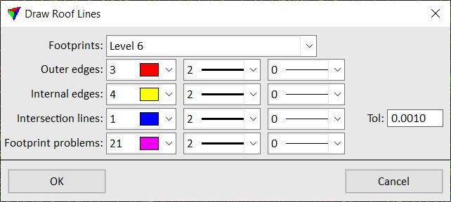
3. Define settings and click OK.
This draws the line elements on the active level of the CAD file.
SETTING |
EFFECT |
|---|---|
Footprints |
CAD file level on which the footprint polygons are drawn. This is required for detecting and drawing Footprint problems. |
Outer edges |
Display color, line weight, and line style of outer edges of the model. Uses the active color table and standard line weights and styles of the CAD file. |
Internal edges |
Display color, line weight, and line style of internal edges of the model. Uses the active color table and standard line weights and styles of the CAD file. |
Intersection lines |
Display color, line weight, and line style of intersection lines of the model. Uses the active color table and standard line weights and styles of the CAD file. The Tolerance value determines up to which maximum positional difference vertices of intersecting planes are considered to be at exactly the same location. |
Footprint problems |
Display color, line weight, and line style of roof lines of the model that do not match to footprint polygons. This highlights problems if a vector model edge is inside the footprint polygon drawn on the Footprints level. Uses the active color table and standard line weights and styles of the CAD file. |
You can undo the drawing of roof lines by using the Undo command of the CAD platform.