

TerraPhoto User Guide
Fields
Fields command determines the attribute fields that are visible in the Tie points window. It lets you select the visibility of information shown in the two list boxes of the window.
To select visible fields:
1. Select Fields command from the View pulldown menu.
This opens the View tie point fields dialog:
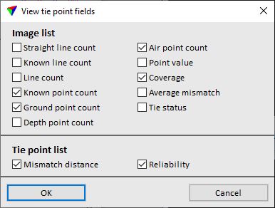
2. Select fields and click OK.
This updates the attribute fields display in the Tie points window.
FIELD |
DESCRIPTION |
|---|---|
Straight line count |
Amount of Straight lines in the image. |
Known line count |
Amount of Known lines in the image. |
Line count |
Amount of Lines in the image. |
Known point count |
Amount of known tie points in the image. Includes Known xyz, Known xy, and Known depth tie points. |
Ground point count |
Amount of Ground points in the image. |
Depth point count |
Amount of Depth points in the image. |
Air point count |
Amount of Air points in the image. |
Point value |
Sum of Tie point values for the image. |
Coverage |
Tie point distribution in the image expressed as percentage value. |
Average mismatch |
Average mismatch distance computed from the tie points in the image. |
Tie status |
Tie status of the image. A = Approved, C = Check. |
Mismatch distance |
Mismatch distance for each tie point pixel. Given in subunits of the CAD file. |
Reliability |
Indicates the reliability of a tie point pixel. Given in numbers for automatically placed tie point pixels. The smaller the number, the more reliable is the pixel. |