

TerraPhoto User Guide
Display mode
Display mode command is used to define what elements are drawn in the orthophoto or colored point cloud previews, if the color point mode is active.
To set the display mode for (ortho) rectification:
1. Select Display mode from the View pulldown menu.
This opens the Color Point Display dialog:
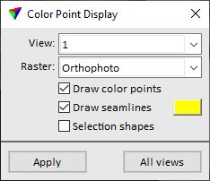
2. Select settings and click Apply or All views.
This updates the display in the selected view or in all CAD file views.
SETTING |
EFFECT |
|---|---|
View |
View for which the settings are applied. |
Raster |
Defines, how images are shown in the view(s): •None - nothing is displayed. •Orthophotos - the rectified raw images are displayed. If thumbnails are available, they are used for the display. •Image assignment - the areas covered by different raw images are displayed with different colors. Each image gets its own color that is stored in the image list file. The color can be changed manually with a data click by using the Change image color command from the Tool menu of the Color points menu bar. •Image quality - the areas covered by different raw images are displayed with a color according to the image’s quality number. The quality number determines the color number used from the active color table of the CAD file. |
Draw points |
If on, color points are shown in the view. |
Draw seamlines |
If on, image seamlines are shown in the view. Click on the color field to define the line color. |
Selection shapes |
If on, all types of selection shapes are shown in the view. |
To set the display mode for point clouds:
1. Select Display mode from the View pulldown menu.
This opens the Color Point Display dialog:
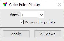
2. Select settings and click Apply or All views.
This updates the display in the selected view or in all CAD file views.
SETTING |
EFFECT |
|---|---|
View |
View for which the settings are applied. |
Draw color points |
If on, color points are shown in the view. |