

TerraModeler User Guide
Output Section Elevations
Not Lite
 Output Section Elevations tool creates a text report which contains surface model elevations from cross sections along an alignment element. The cross section positions for the output can be at fixed intervals or only at locations where there is a change in the shape of the surface model. You can view the report, print it out, or save it as a text file.
To output elevations from alignment sections:
1. Select the Output Section Elevations tool.
2. Identify the alignment for the sections.
3. Accept the highlighted alignment.
This opens the Output Section Elevations dialog:
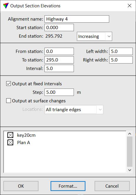
4. Define settings.
5. Select surfaces from the list in the lower part of the dialog. Only selected surfaces are included in the output.
6. (Optional) Click on the Format button to select options controlling the Section output format.
7. Click OK to the Output Section Elevations dialog.
This opens a report window which contains the output information. Use the commands from the File pulldown menu to print the report or save it into a text file.
Setting |
Effect |
|---|---|
Alignment name |
Descriptive name for the alignment in the report. |
Start station |
Station value at the start point of the alignment element. |
End station |
End station value defined by the length of the alignment element: •Increasing - station values are increasing from start to end station. •Decreasing - station values are decreasing from start to end station. |
From station |
First station on which a cross section is included in the output. |
To station |
Last station from which a cross section can be included in the output. |
Interval |
Station interval between two successive cross sections. Determines the number of cross sections in the output. |
Left width |
Cross section width perpendicular to the left from the alignment. |
Right width |
Cross section width perpendicular to the right from the alignment. |
Output at fixed intervals |
If on, output surface elevations at a fixed interval along the cross section. The Step field determines the size of the interval. |
Output at surface changes |
If on, output surface elevations at locations where there is a change in the surface model: •All triangle edges - locations where the alignment intersects a triangle edge. •Breakline edges - locations where the alignment intersects a breakline edge. •Slope changes - locations where the slope changes more than a given limit. •Peaks and pits - local maximum and minimum elevations. |
The Section Output Format dialog provides some choices for formatting the output of the Output Section Elevations tool.
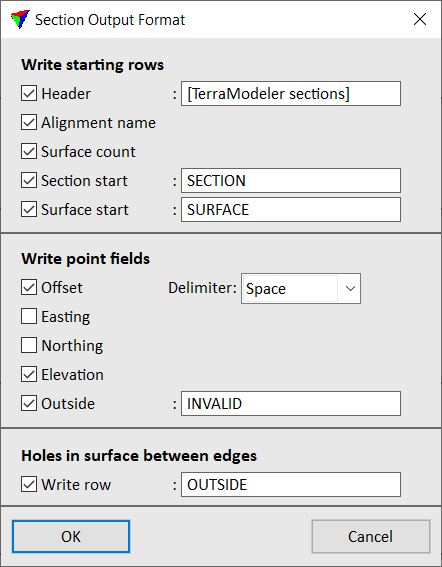
The output file may contain some starting rows including Header, Alignment name and Surface count. Each generates one output line if selected.
If Section start is switched on, a line is written to indicate the start of a new cross section. You can specify the prefix text appearing before the station value.
If Surface start field is switched on, a line is written to indicate the start of a new surface. You can specify the prefix text appearing before the surface name.
Each elevation position of a cross section is written in one line. You can select what information fields are included in the output: Offset, Easting, Northing, and Elevation.
When using Output at fixed intervals, the application computes elevation positions at fixed intervals along the cross section. Some of these positions may be outside the surface model. The Outside field determines if outside positions are written and what text is used for the output.
When using Output at surface changes with All triangle edges as locations, the application generates output positions only at triangle edges. The alignment may go outside the surface model in between the generated positions. If Write row is on, the application outputs a line between the positions to indicate that the cross section is outside the surface model or goes through a hole in the model.