

TerraMatch User Guide
Import points
Import points command starts the import of control measurements that have been measured on corners or end points of paint markings, on signal marker locations or on target objects. The import results in tie lines of the type Known xyz, Known xy, Known z, or Elevation point.
The control measurements can be provided in a text file where each line includes the separated x, y, and z coordinates for one control point. Another option are point elements drawn in the CAD file at the control measurement locations.
The command requires that a project is loaded in TerraScan where the laser data provides the input for placing the tie lines. If signal markers are used for placing Known xyz or xy points, the shape of the signal marker must be defined in TerraMatch Settings.
To import control measurements as points:
1. (Optional) Select the control points in the CAD file if you want to import the control points based on selected vectors.
2. Select From text file or From selected vectors command from Import points command of the File pulldown menu.
This opens the Import Points dialog:
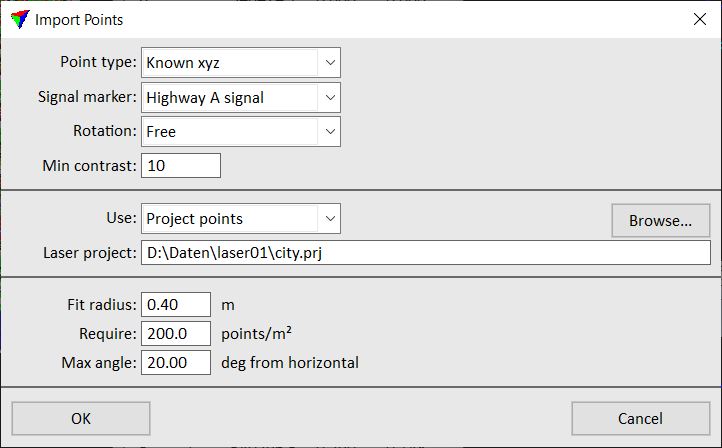
Setting |
Effect |
|---|---|
Point type |
Type of tie lines that are created from the control measurements. |
Signal marker |
Signal marker or target object name defined in TerraMatch Settings, or built-in target name. Required for importing Known xyz or Known xy points. •Deutche Bahn signal - metal plate signal marker standardized in German railroads. |
Rotation |
Defines the rotation for a signal marker: •Free - the signal marker can be rotated freely compared to the travel direction. •Travel direction - the rotation of the signal marker is fixed. The travel direction is extracted from the closest trajectory. |
Max range |
The maximum distance from scanner to the targets. The search skips targets observed from further distance as lower observation quality is expected. |
Min contrast |
Intensity contrast between bright parts of a signal marker and the dark background. |
Max angle |
The target is expected to face towards the trajectory. The search excludes found targets with bigger rotation to avoid low quality observations. |
Use |
Laser points used for placing the tie lines: Project points (Not UAV) or Loaded points. |
Laser project |
Path to a TerraScan project. This is only active if Use is set to Project points. |
Fit radius |
Area within which points are used to calculate the tie line location. |
Peg length |
The reference bolt length of the targets. This is available only if Signal marker is set to Deutche Bahn signal. |
Require |
Point density required for placing the tie line. |
Default lean |
The expected vertical lean of the targets. This is available only if Signal marker is set to Deutche Bahn signal. |
Max angle |
Maximum allowed angle of the surface at a tie line location. |
Max lean |
Maximum allowed vertical lean of the targets. Targets with higher lean angle are excluded to filter bad findings. This is available only if Signal marker is set to Deutche Bahn signal. |
3. Define settings and click OK.
If the import is based on selected vectors, the software starts the import and places the tie lines at the control measurement locations. Continue with checking the tie lines and placing tie line positions manually where the automatic placement failed.
If the import is based on text file, another dialog opens for selecting the text file.
4. Select the text file and click Open.
This starts the import and the software places tie lines at the control measurement locations. After the import has finished, an information dialog is shown. It displays the number of created known points vs. the number of control measurements found in the text file or selection set.
5. Continue with checking the tie lines and placing tie line positions manually where the automatic placement failed.