

TerraMatch User Guide
ALS Calibration
TerraMatch can be used to solve the mirror scale parameter and the misalignment between the laser scanner and the inertial measurement unit (IMU). The misalignment is expressed as heading, roll and pitch angular correction values which need to be known for every laser scanner system.
Different laser scanners may require additional calibration parameters as well. Those must be solved using more manual methods with TerraScan or with system specific software.
Flight pattern
The optimal site for a calibration flight contains both flat and sloped surfaces which do not have disturbing surface objects such as low vegetation. The most commonly used target area for calibration is an airport as it is easily accessible and most often contains suitable surfaces, such as the run ways and sloped building roofs.
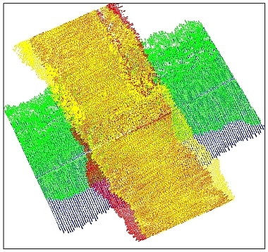
The minimum flight pattern for calibration is four flight passes over the same area in a cross like pattern where the slopes surfaces are located at the center of the cross, as shown in the figure below.
You may consider some additional flight passes which may improve the quality of the calibration:
•An additional flight pass for which the sloped surfaces are located at the right of left edge of the corridor covered. This helps to differentiate pitch and heading from each other.
•Additional flight passes at a higher or a lower altitude.
Processing steps
The processing of a calibration flight can be outlined with the following steps:
1. Solve GPS trajectories.
2. Compute xyz laser points with system specific software using the last known calibration values.
3. Import trajectories into TerraScan and transform them to any coordinate system.
4. Split any trajectories which overlap themselves.
5. Import time-stamped laser points into TerraScan and transform them to the same coordinate system.
6. Make sure that the flightline numbering of the laser points matches trajectory numbers (in TerraScan, use Deduce using time command from Line pulldown menu).
Continue according to the matching method.
Surface-to-surface matching:
7. Classify low points.
8. Classify ground separately for each flightline.
9. (Optional) Classify some buildings separately for each flightline.
10. Smoothen ground surface if most of it is asphalt or some other hard surface.
11. Run Find Match and solve for heading, roll, pitch and mirror scale corrections for the whole data set.
12. Add the result values to the correction values used when computing the xyz points in step 2.
Tie line-based matching:
7. Search for tie lines of type Surface lines. This does not require any classification of the laser points.
8. Run Find Tie Line Match and solve for heading, roll, pitch and mirror scale corrections for the whole data set.
9. Add the result values to the correction values used when computing the xyz points in step 2.
The laser scanner may have operation modes which make calibration easier such as profile mode. If such a mode is available, it should be used to solve the pitch correction value first. Then TerraMatch should be used to solve for heading and roll correction only.