

TerraMatch User Guide
Add ground point
Add ground point command lets you place a tie line of the type Ground point.
To add a ground point:
1. Select Add ground point command from the Line pulldown menu.
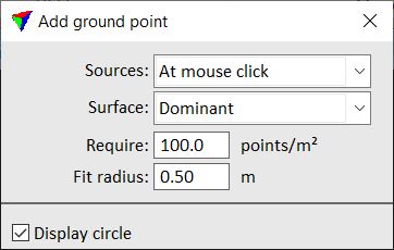
This opens the Add ground point dialog:
Setting |
Effect |
|---|---|
Sources |
Determines where the software looks for data for placing a tie point: •At mouse click - data from lines/scanners with required point density around the data click location is considered. This is the preferred setting. •Within max error - data from all lines/scanners are considered for tie point placement if they are within the maximum error limits given in the tie line settings. This slows down the tie point placement and should be used only in exceptional cases (e.g. tunnel data sets with large mismatch). |
Surface |
If a point cloud contains multiple surfaces at the location of a tie point, the tie point is fitted to: •High - the highest surface. •Dominant - the dominant surface. Use this in all cases where there is only one surface in a point cloud at a tie point location. •Low - the lowest surface. |
Require |
Point density required for placing the tie point. |
Fit radius |
Area within which laser points are used to calculate the tie point’s elevation. |
Display circle |
If on, a circle of the specified Diameter is displayed at the mouse pointer location. This helps to place a tie point accurately, for example on circular objects. |
2. Define settings that fit to the laser data.
3. Select an approximate location for the tie point in the Full view.
This updates the Entry view and Detail view and adds the tie point to the list.
4. Place the tie point in the Entry view according the the laser data for each tie point position.
If you are not able to place all tie point positions, you can skip a position by selecting the next observation for this tie point. Then use the Clean command to remove undefined positions.