Camera view / Create
Create command from the Camera View sub-menu sets up a window as a perspective view displaying the world as seen by a camera when recording one of the raw images. In addition to displaying the image file, a camera view can display laser points and vector elements projected into the same perspective view.
CAD file views can act as orthographic or as perspective views. An orthographic view is like a map. There is no specific viewer location and equal size objects are drawn with the same size on the screen. A perspective view has a specific viewer or camera location. Objects close to the viewer occupy a larger space on the screen than distant objects. Perspective views correspond to the way we see the world.
If a panoramic camera is used, TerraPhoto opens another dialog for controlling the camera view. The dialog lets you rotate the panoramic view left and right, move to the previous/next image, and change the vertical field of view. By default, the field of view is set to 60 degree. Depending on the view size, the panoramic image may look stretched and you may change the field of view to another value.
To create a camera view:
1. Select Create camera view command from the View pulldown menu.
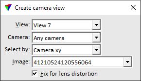
The Create camera view dialog opens:
2. Select the target view in the View field.
If the mouse pointer is moved inside a view, the application displays the footprint of the closest image.
3. Identify a location with a data click to select which image to use.
This sets the Camera attribute on in the view. The camera location is set to the xyz position of the camera when the selected image was captured. The selected image is displayed in the view as well as laser data and vector elements, if available.
The display of laser data can be managed using the Display dialog of TerraScan. The display of vector elements is organized in the Level Display dialog of the CAD platform.
SETTING |
EFFECT |
|---|---|
View |
CAD file view for displaying the camera view. |
Camera |
Name of the camera from which to display the images. Alternatively, images from Any camera can be selected for display. |
Select by |
Defines the selection method of images for display: •Camera xy - the image with the camera xy position closest to the mouse pointer is selected. •Target xy - the image with the target xy position closest to the mouse pointer is selected. •Target xyz - the image with the target xyz position closest to the mouse pointer is selected. |
Image |
Number of the image selected for display. The selection list contains all images of the active image list. |
Fix for lens distortion |
If on, the image is displayed with applied lens distortion correction. The lens distortion is defined in the TerraPhoto camera dialog. |
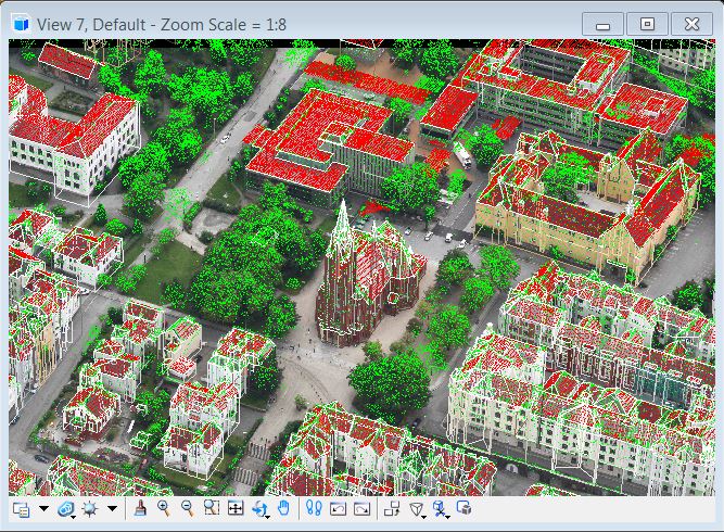
Camera views are excellent for comparing laser data and/or vector elements to images. You can compare any objects regardless of the elevation - you are not limited to ground objects as with rectified images. The figure below illustrates a camera view of an oblique image overlayed with laser data (points on roofs and high vegetation) and 3D vector models of buildings.
For camera views of panoramic images, the Panoramic View dialog opens:
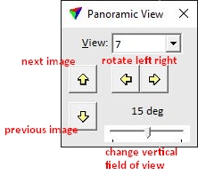
4. Use the user controls of the dialog in order to rotate the panoramic view, move to the previous/next image, and change the vertical field of view.